• Portfolio
  • Aviation
  • Blog
  • About
Menu

David S Miller

  • Portfolio
  • Aviation
  • Blog
  • About
iso_perpective_render.JPG
iso_exp_perpective_render.JPG
 Opening

Opening

 Exposed Control Rods

Exposed Control Rods

iso_perpective_render.JPG iso_exp_perpective_render.JPG  Opening  Exposed Control Rods

Isolating Pure Bending in Optical Fibers

February 20, 2016

One of the grad students from the nanophotonics lab I developed the microbend apparatus for contacted me regarding a question he had. He was trying to isolate bending and torsional loads in optical fibers to investigate their effects. Introducing pure bending in a fiber is difficult because the fibers have very little torsional stiffness. It's easy to eliminate bends to a twisted fiber by simply adding a bit of tension to the ends. But how do you eliminate twist? There is so little stiffness that you cannot rely on the restoring torque to eliminate small twists in the fiber. The current solution is to coil the fiber very loosely (coiling is just one very long continuous bend) whatever twist is inadvertently introduced by the act of coiling will distribute itself along the length of the entire fiber. In contrast, in fiber optic gyroscope winding, because the coils are so tight, the minor twists in the fiber get trapped between turns of the coil, leaving behind localized residual torsions in the fiber. 

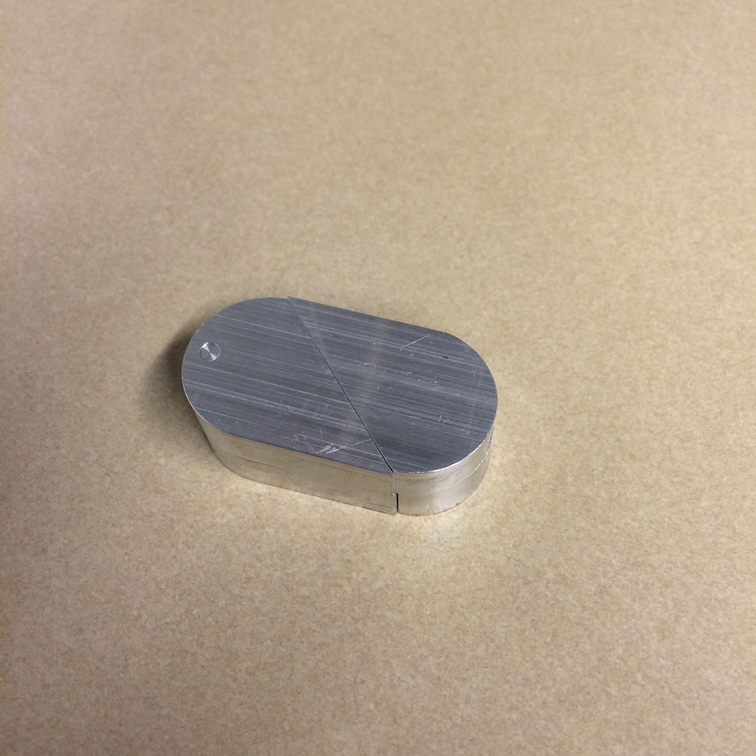
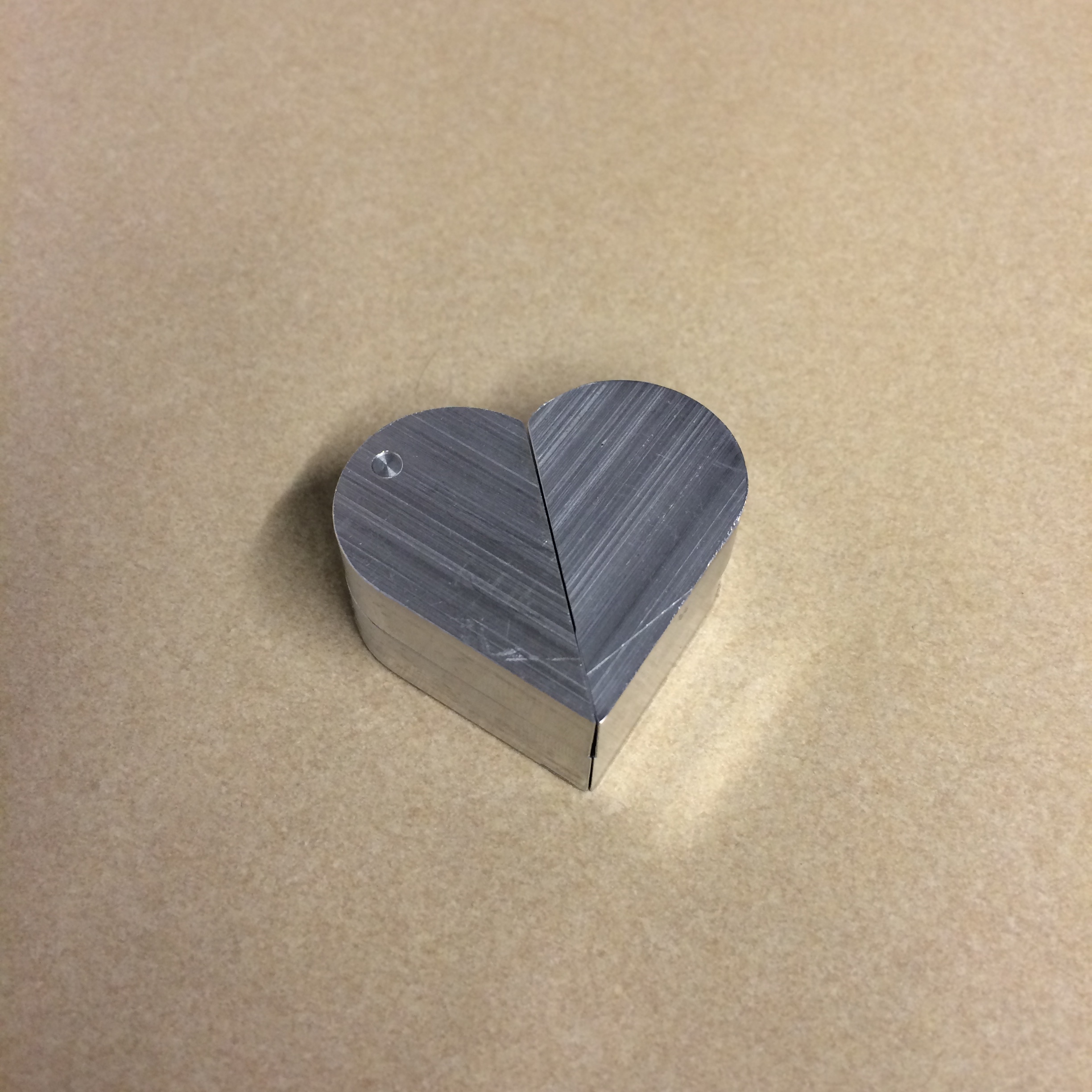
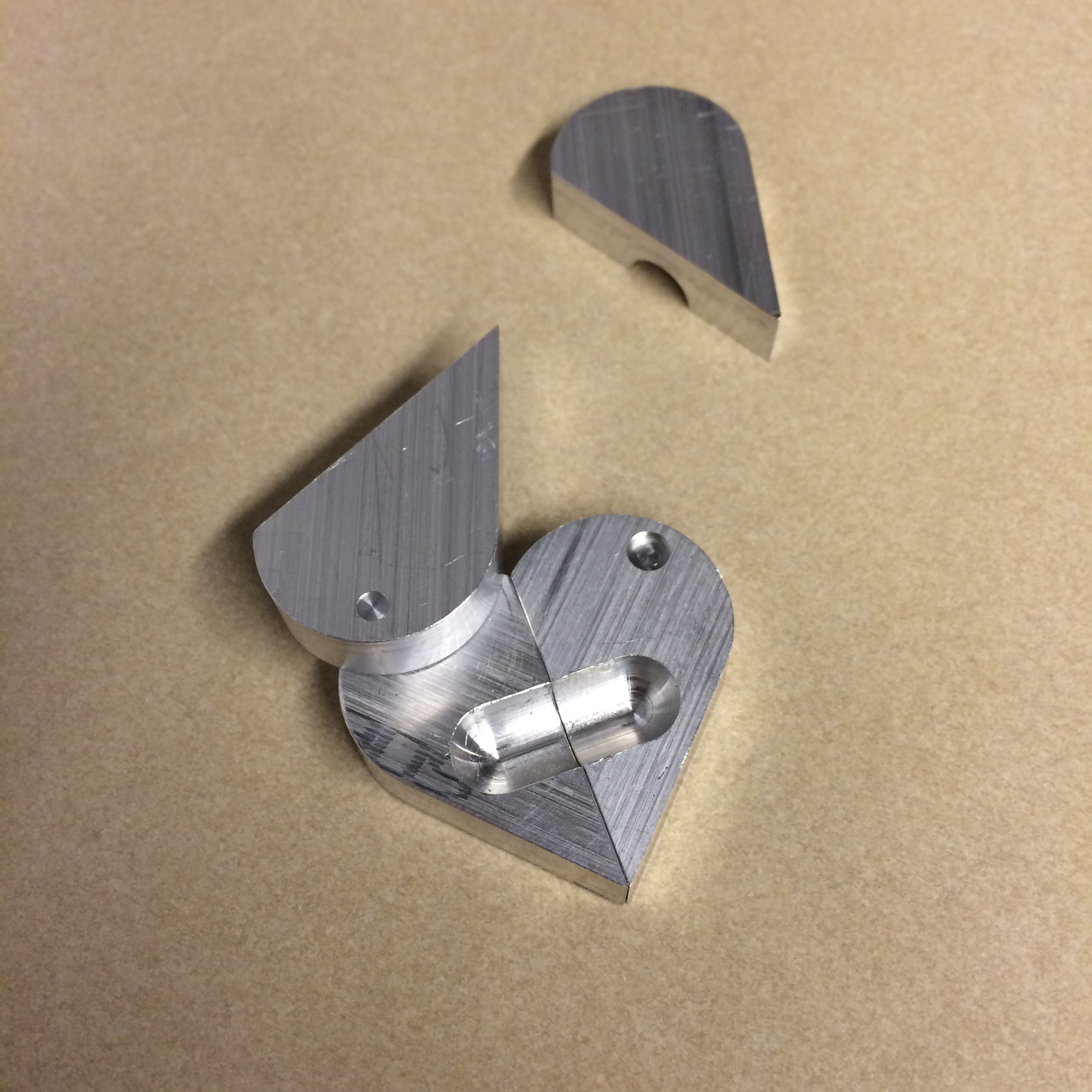
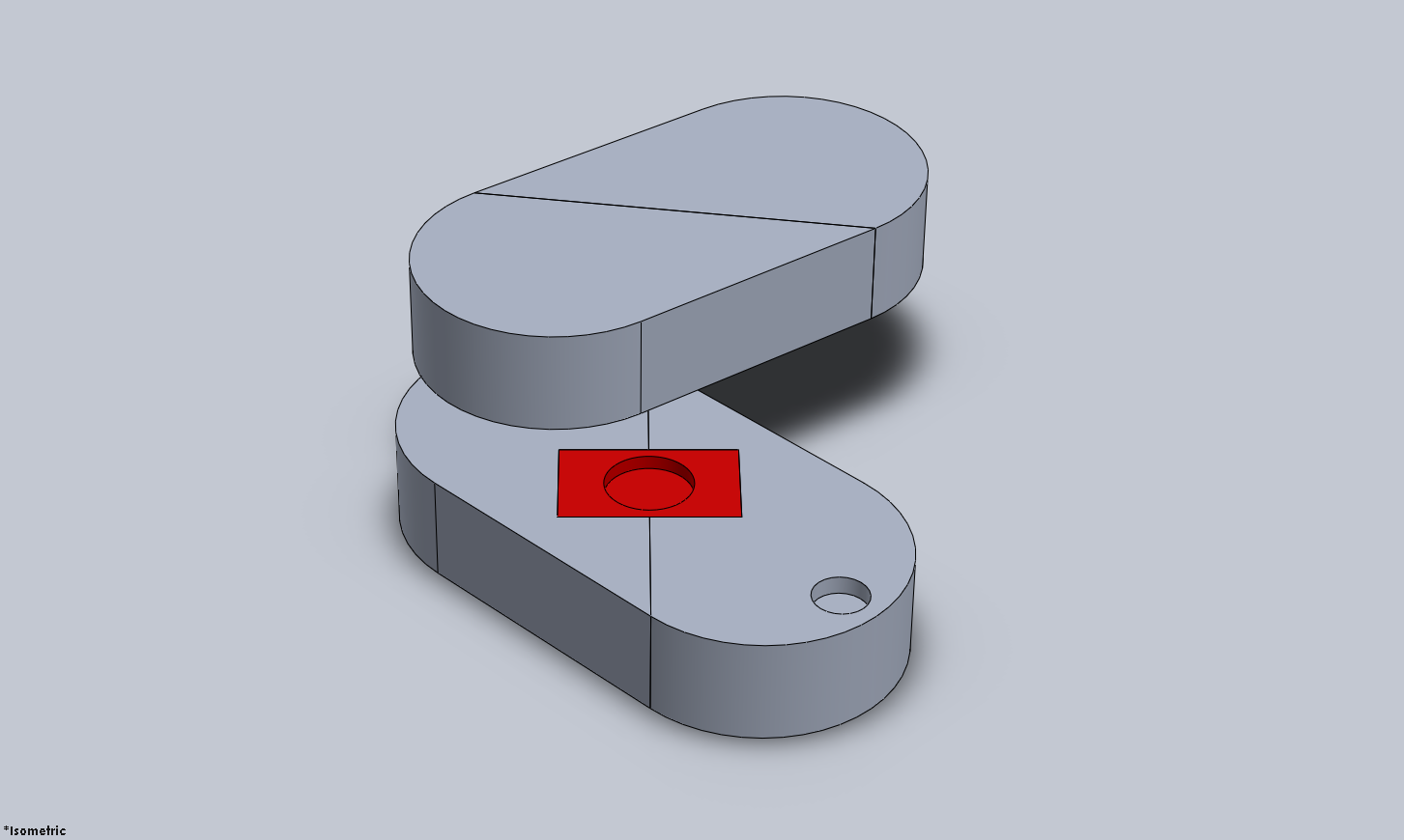
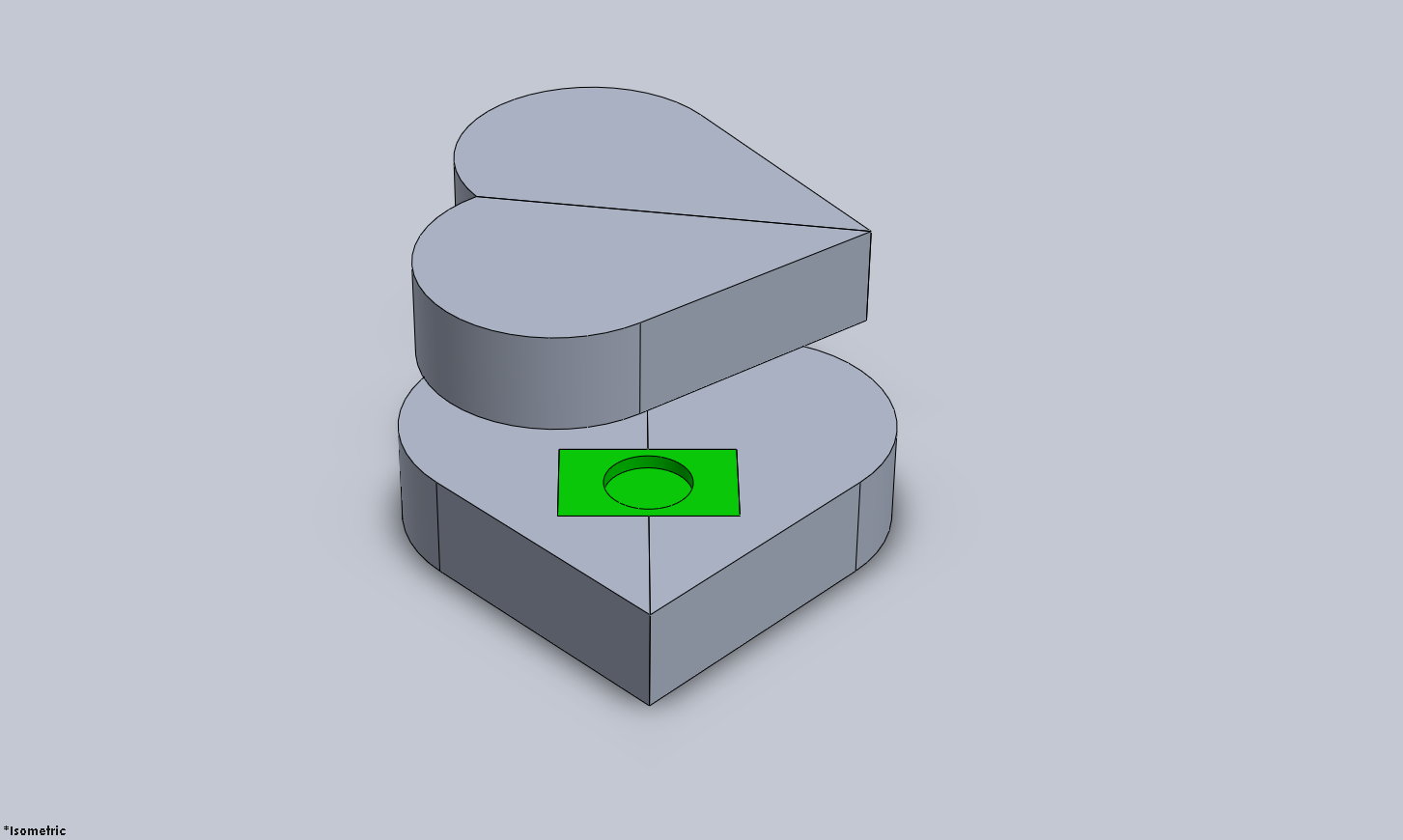
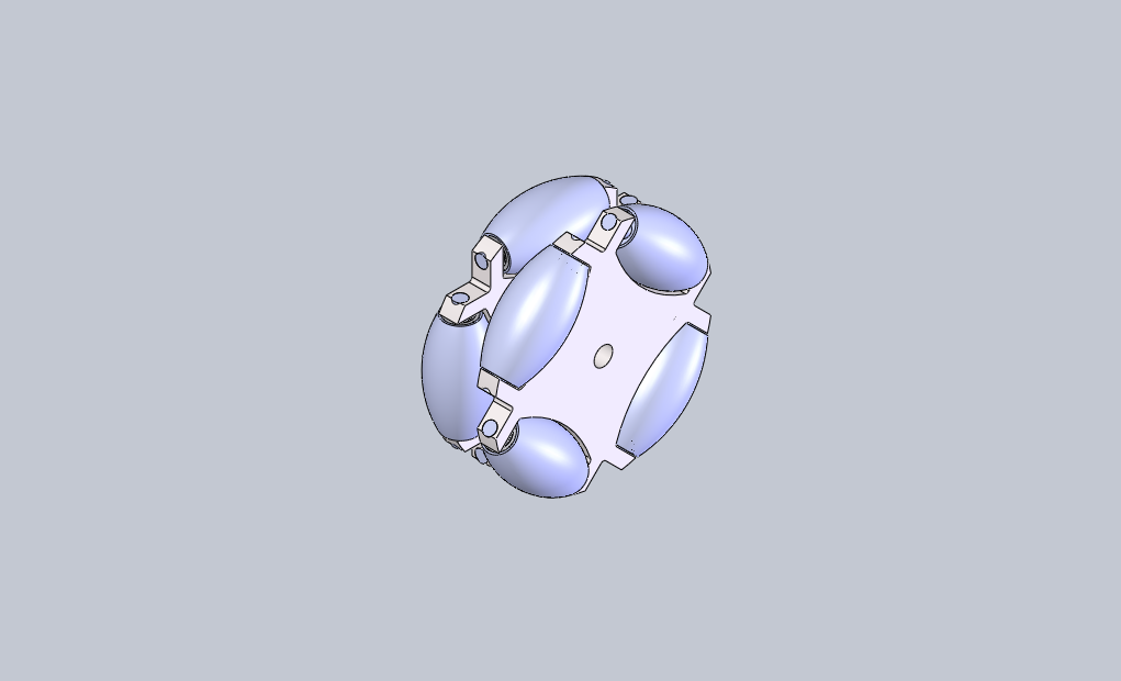
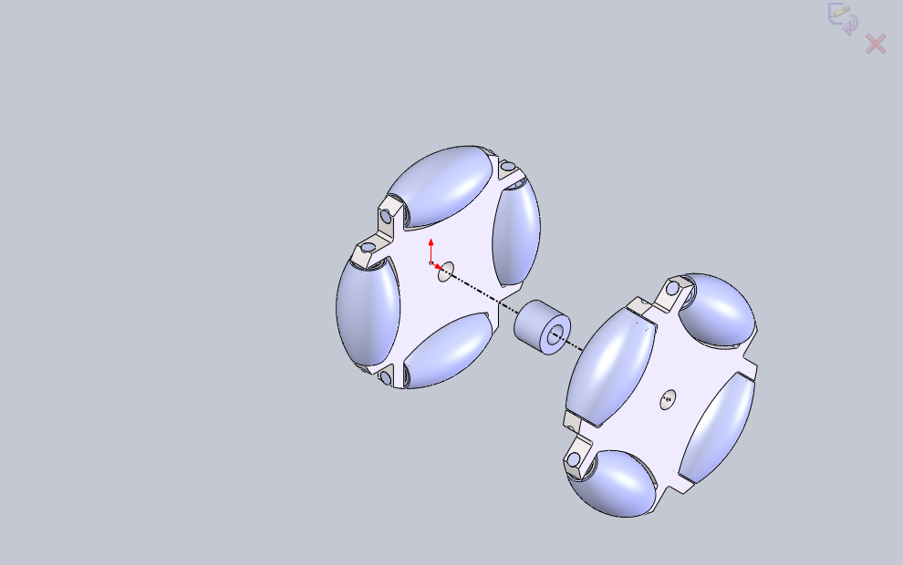
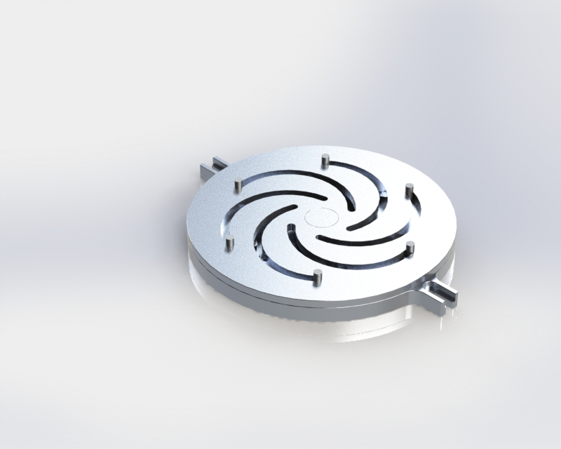
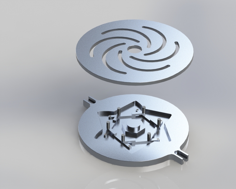
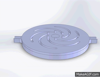
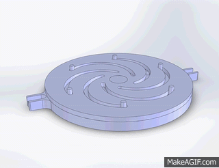
The downside to a loose coil is that it is very hard to get each turn in the coil to the same diameter. A constant bending radius is required for accurate measurements. We decided to use an iris diaphragm mechanism to control the diameter of 6 pins, which the fiber will loosely be wrapped around as guides. This way, a very minimal amount of tension could be used to make sure the coils are all the same diameter, and the diameter can be adjusted using the iris mechanism. To go along with this, it would be helpful to have a limited slip fiber clamp and constant force spring loaded spool so the diameter could be adjusted either direction without having to manually pick up slack in the fiber or loosen the coils to reduce the tension. 

One other alternative to this 'loose coil' solution is to actively measure and correct the fiber twist. However, this method seems overly complex. It really depends on how much twist is tolerable. Once that is quantified, we will be able to determine what type of solution is required. I have a feeling the tolerance will not be so tight as to necessitate some type of active system. But I wonder if there is a better solution for an active system? Perhaps if instead of wrapping the fiber around pins, we could wrap it around an expanding cylinder controlled by the iris mechanism. But I have no idea how that could work. Time to start brainstorming...

$\setCounter{0}$
In Personal Projects Tags Optics, Fiber, Mechanisms, kinematics, SolidWorks, Design
Comment
IMG_7073.jpg
IMG_7074.jpg
IMG_7075.jpg
IMG_7076.jpg
IMG_7073.jpg IMG_7074.jpg IMG_7075.jpg IMG_7076.jpg

Illusionist's Locket Pt. 3

February 16, 2016

I machined the first parts of a prototype today. I used a 3/8" ball-mill to get the central channel for the barrel pivot to rest in. I'm trying to see if there is a better way to do this, as the ballmill leaves a circular edge when I'd rather have a flat face. Also, slight errors in the depth of the ballmill correspond to the channel for the barrel not being cylindrical. There are still many improvements to be made!

$\setCounter{0}$
In Personal Projects, Illusionist's Locket, Machining Projects Tags CNC, Machining, SolidWorks
Comment
 Oval configuration: red barrel visible.

Oval configuration: red barrel visible.

 Heart configuration: green barrel visible.

Heart configuration: green barrel visible.

 Here you can see how the barrels move when you rotate the mechanism from the oval to the heart or vice versa.

Here you can see how the barrels move when you rotate the mechanism from the oval to the heart or vice versa.

 Mystery solved! There's no magic here.

Mystery solved! There's no magic here.

image5.png
 Oval configuration: red barrel visible.  Heart configuration: green barrel visible.  Here you can see how the barrels move when you rotate the mechanism from the oval to the heart or vice versa.  Mystery solved! There's no magic here. image5.png

Illusionist's Locket Pt. 2

February 11, 2016

Today I was able to reverse engineer the mechanism that switches the photos in the locket depending on the configuration. The key is having a two-part barrel that the halves pivot about. The two parts of the barrel are not attached, allowing them to separate when the locket is opened. Each half of the barrel is fixed to one of the movable heart pieces, allowing the other heart pieces to rotate around them, and allowing the barrel halves to slide over each other. 

The next step is to incorporate this mechanism into my existing design. I will probably need a few more magnets to hold the locket closed. I will also modify some of the geometry of the barrels and the barrel slots so they are machinable. 

$\setCounter{0}$
In Personal Projects, Machining Projects, Illusionist's Locket Tags Design, Mechanisms, Reverse Engineering, CAD, SolidWorks
Comment
 Heart configuration. Magnets are attracted to each other, so the configuration is stable.

Heart configuration. Magnets are attracted to each other, so the configuration is stable.

 Rotating the two halves

Rotating the two halves

 Oval configuration. Magnets now repel each other, so the two halves can easily be pulled apart,

Oval configuration. Magnets now repel each other, so the two halves can easily be pulled apart,

 Disassembly of the two halves reveals hidden pocket for a ring, note, etc.

Disassembly of the two halves reveals hidden pocket for a ring, note, etc.

 "MD" Side

"MD" Side

 "DM" Side

"DM" Side

 In the oval configuration.

In the oval configuration.

 Heart configuration. Magnets are attracted to each other, so the configuration is stable.  Rotating the two halves  Oval configuration. Magnets now repel each other, so the two halves can easily be pulled apart,  Disassembly of the two halves reveals hidden pocket for a ring, note, etc.  "MD" Side  "DM" Side  In the oval configuration.

Illusionist's Locket

February 9, 2016

This is a present I plan on making for my girlfriend for Valentine's Day. It is a metal heart made of two halves that are connected with a dowel pin and magnets. When the two halves are arranged in the heart configuration, the magnets attract each other and so the configuration is stable. When you twist the halves apart, the halves take the form of an oval. With the magnets' positions switched, the halves repel each other, allowing the user to separate the halves and gain access to the secret pockets inside each half. The secret pockets can be used to small rings, a small note, etc.

I've also decided to take advantage of the fact that our initials form a palindrome. If our initials are engraved a certain way on the two halves, on one side of the heart configuration the letters read "MD" (her initials) and on the other side the initials read "DM" (my initials). When rotated to the oval configuration, both sides are the same but are upside down relative to each other. So it reads "DM" or "MD" depending on how you look at it. I like to think of it as being symbolic of our partnership together.

Manufacturing should be relatively simple. The two halves can be CNC'd out of bar stock. I made the angle on each half 45 deg so that any standard shop gauge block could be used to mount the middle face parallel to the table of the mill for drilling the holes and milling the slot. I plan to use a 1/8" steel dowel pin for the center pivot shaft which can be turned on the lathe. Adhesive backed neodymium magnets will be used for retention. If I decide to do the engraving I will need to make some sort of fixture or jig for a flip milling operation on the reverse side of each half of the heart. Hopefully I can make a simple jig with some locating pins mounted on the mill table.

Note: This design is inspired by an Instructable I remembered seeing a while back. The author of the Instructable credits the design to a scene from the movie "The Illusionist". As you can see, the locket in the movie has 2 additional hinges that allow the locket to swing open in both the oval and heart configuration. The "illusion" is that when you open the locket in one configuration, one person's image appears. But when you open the locket in the other configuration, the other person's image appears. And the baffling thing is, it's hard to understand how twisting the locket from the heart to the oval configuration doesn't rip the picture in half. This is a *greatly* simplified version where there really is no illusion. I will use this design as a starting point and hopefully be able to design a locket that has the full functionality as seen in the movie.

$\setCounter{0}$
In Personal Projects, Illusionist's Locket, Machining Projects Tags Machining, CNC, SolidWorks, CAD
Comment
 Rendering of the detailed assembly. Bearings and fasteners have been specced.

Rendering of the detailed assembly. Bearings and fasteners have been specced.

image1.png
image3.png
image.png
image4.png
 Rendering of the detailed assembly. Bearings and fasteners have been specced. image1.png image3.png image.png image4.png

Omniwheel Design

January 12, 2016

Currently working on a high load capacity omniwheel design for our circuit breaker removal robot (BreakerBot). Off the shelf omniwheels of this load capacity (750lb) are very expensive! This design is an exercise to see if constructing our own wheels is a feasible solution. Our other options are to choose an alternative drive train system that doesn't require these expensive and complex omniwheels. However, those systems are either non-holonomic (ackerman steering) or even more complex (swerve drive). I am hoping that we will be able to use these wheels with sort of H-drive system. We do not need full holonomic control, but the ability to strafe and turn on a point would be very useful for aligning the robot with the breaker's cubicle for extraction. 

$\setCounter{0}$
In BreakerBot Tags robotics, omniwheel, BreakerBot, Design, SolidWorks
Comment

Blogpost Search

Blogposts by Category

Select Category
  • Academic Projects
  • Aviation
  • BreakerBot
  • Engineering Education
  • Illusionist's Locket
  • MATLAB Projects
  • Machining Projects
  • Personal Projects

Archive

  • May 2024
  • December 2019
  • November 2019
  • September 2019
  • April 2017
  • January 2017
  • August 2016
  • May 2016
  • April 2016
  • March 2016
  • February 2016
  • January 2016
  • November 2015
  • October 2015
  • June 2015
  • April 2015
  • February 2015
  • January 2015

Copyright © David Miller 2019