• Portfolio
  • Aviation
  • Blog
  • About
Menu

David S Miller

  • Portfolio
  • Aviation
  • Blog
  • About
 Ready to cast the mold media. Just need some mold release.

Ready to cast the mold media. Just need some mold release.

 Gluing the box that will become the mold cavity.

Gluing the box that will become the mold cavity.

 Milling the positive from aluminum.

Milling the positive from aluminum.

 Ready to cast the mold media. Just need some mold release.  Gluing the box that will become the mold cavity.  Milling the positive from aluminum.

Quantum Dot Lite Brite Pt. 2

April 15, 2016

The specs for this design have been developed. Recently I've been working on making the molds to cast the QD plastic in. I purchased a tin-cure silicone molding media which meets the temperature requirements of the vacuum oven the plastic will be cured in. I selected tin cure over platinum cure because we have access to a vacuum chamber to de-gas the molding media as it cures, and it's a bit cheaper than the platinum cure. It also works with a wider variety of materials. The library life is not as long as the platinum cure, but that is not really a concern for this application.

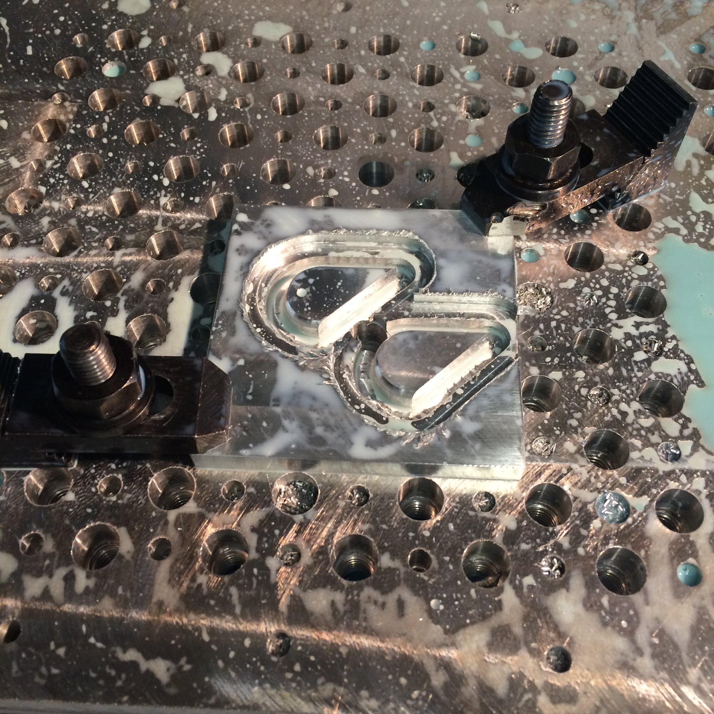
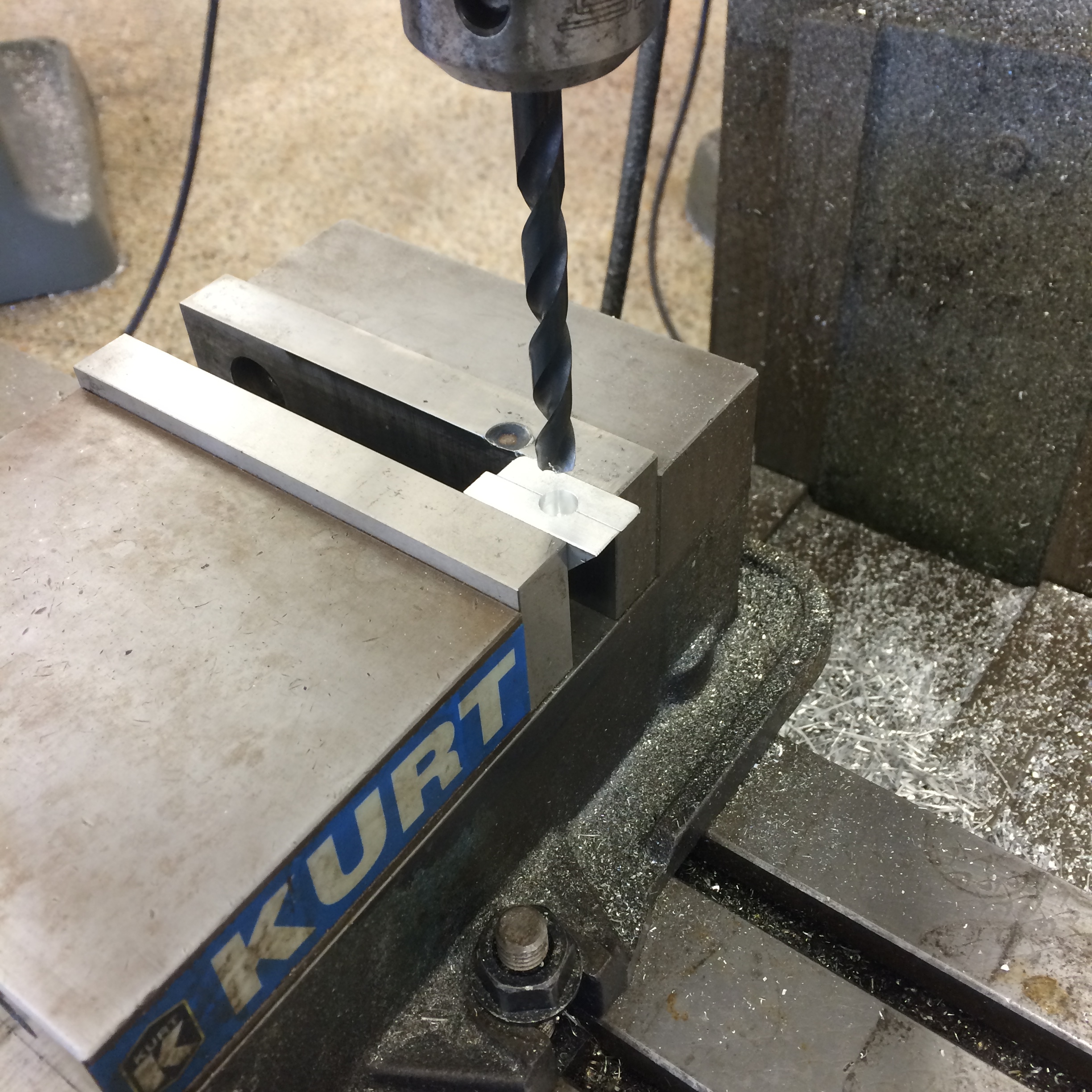
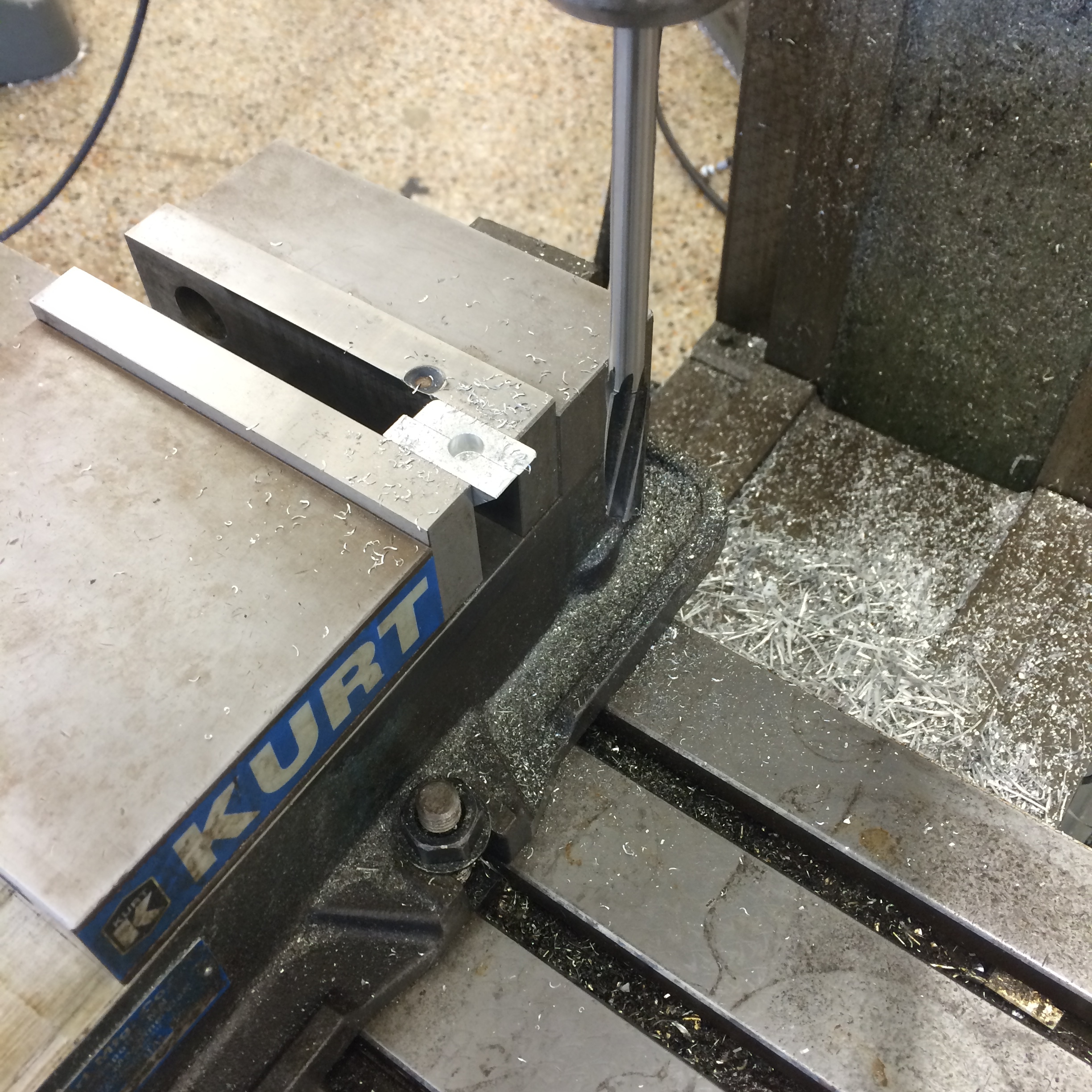
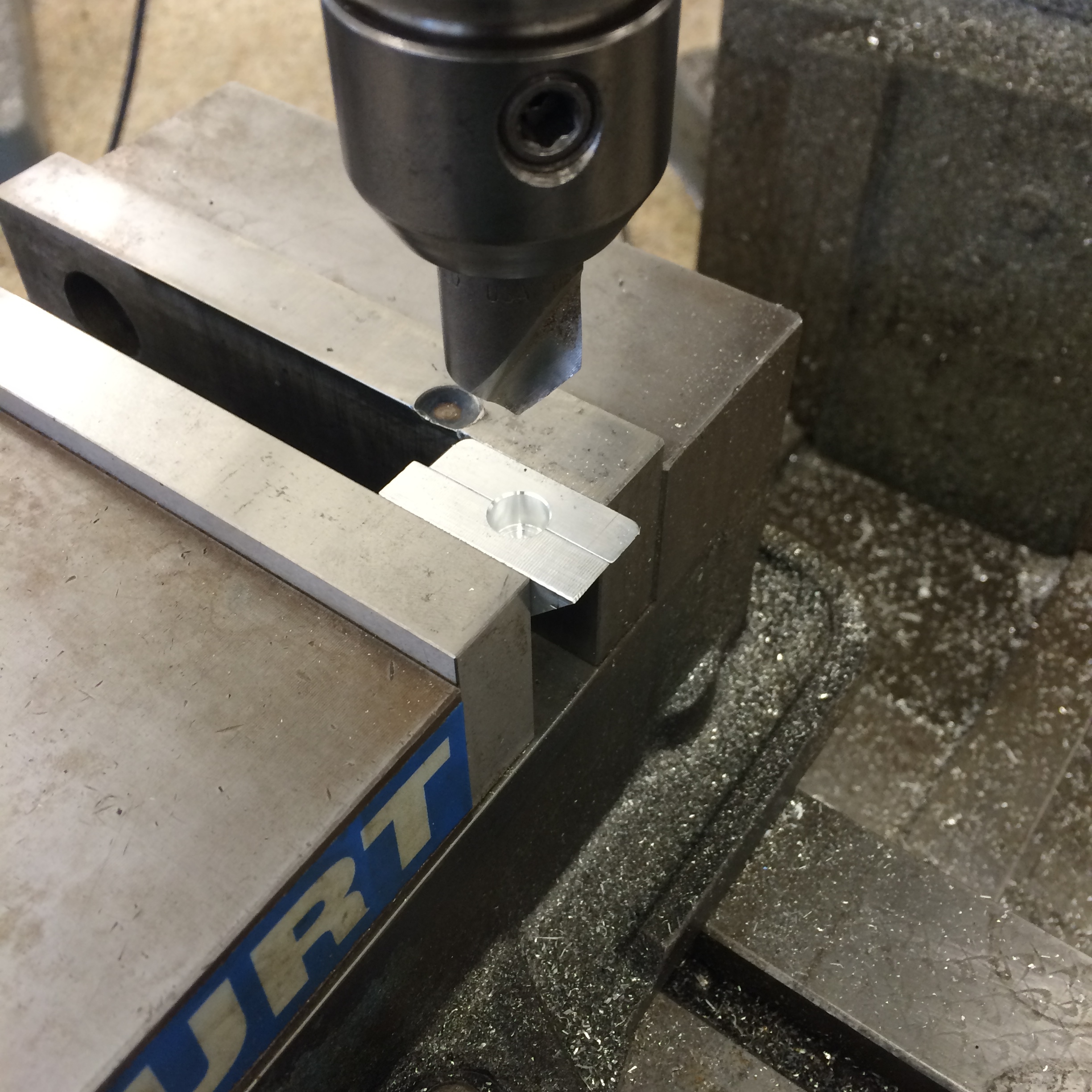
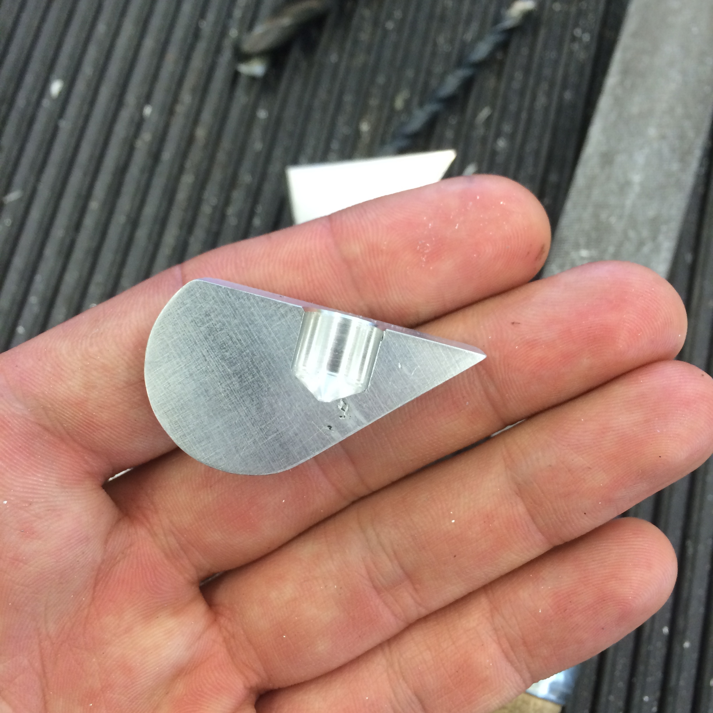
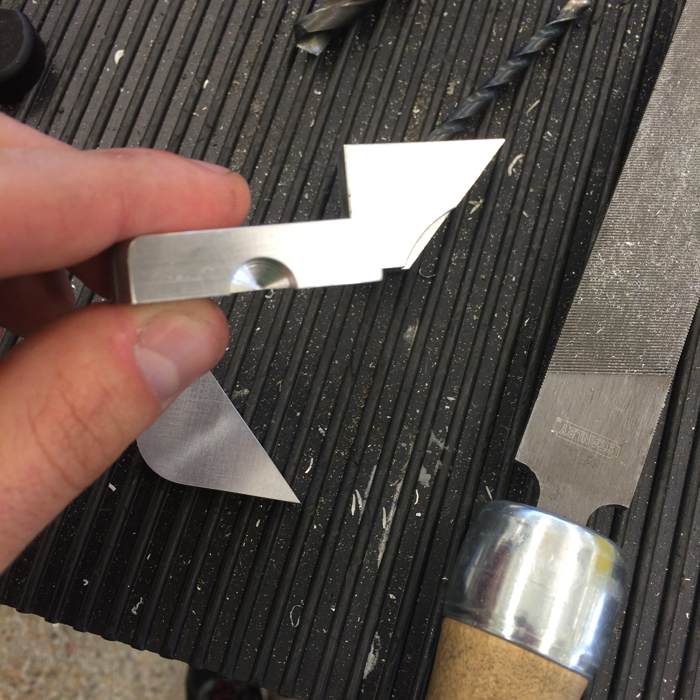
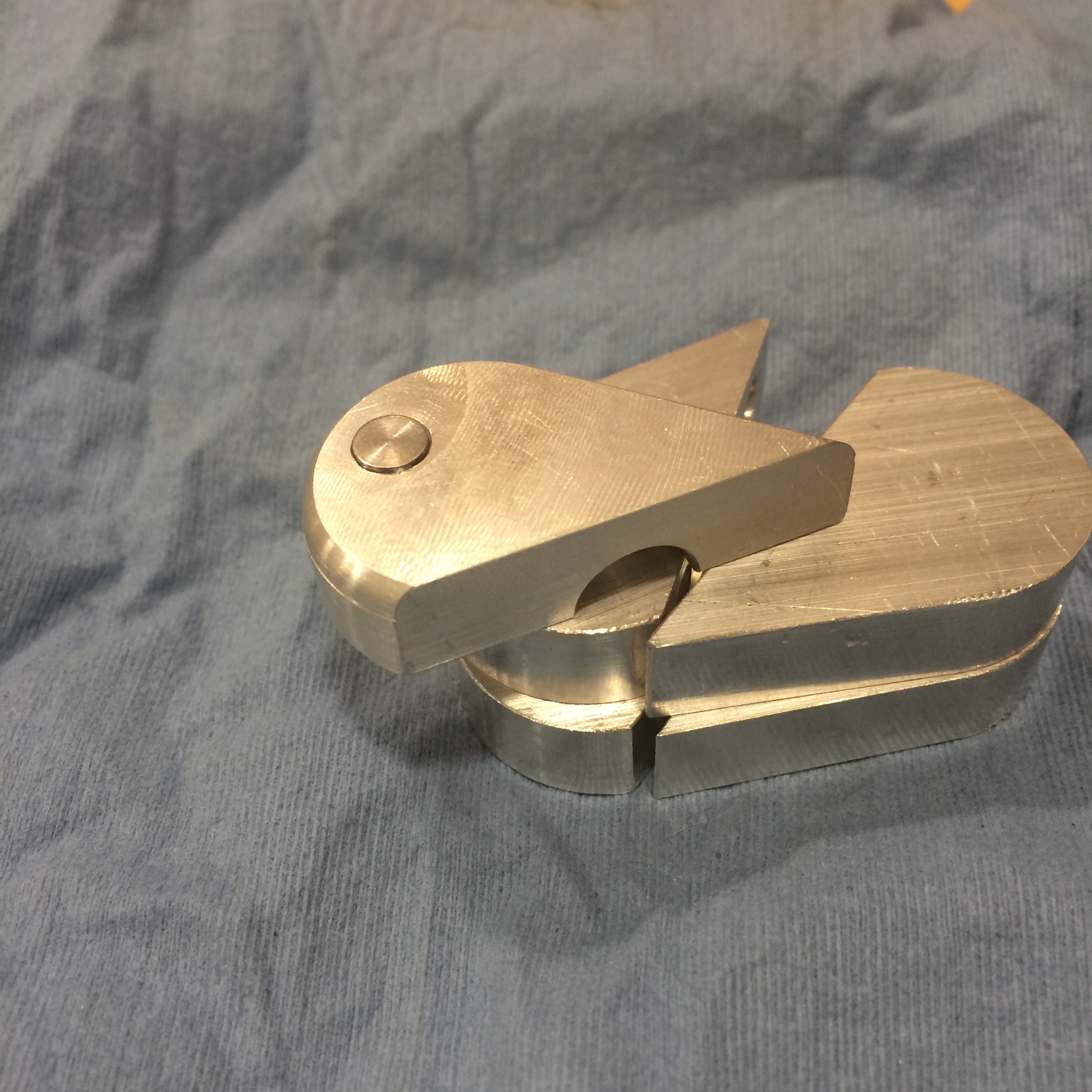
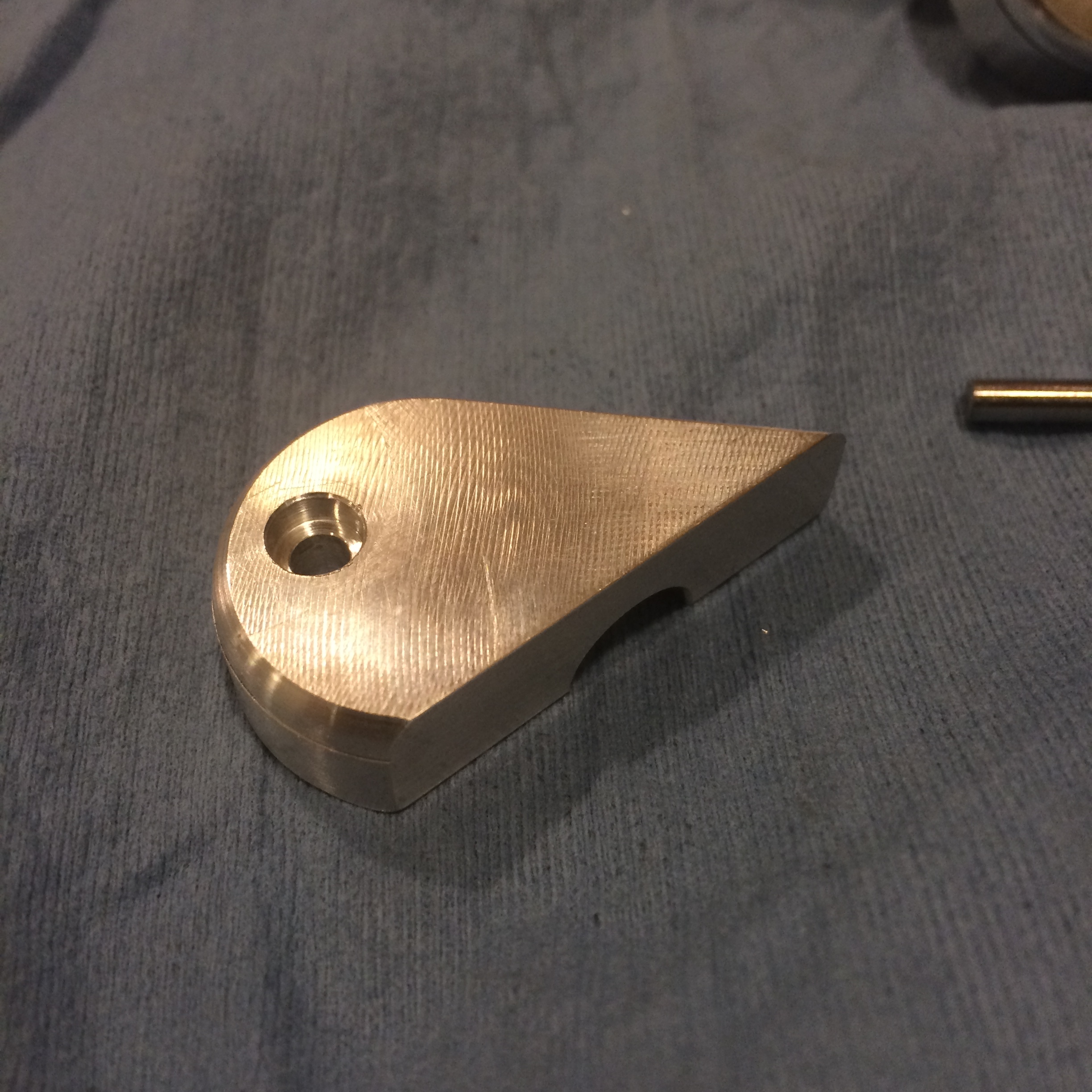
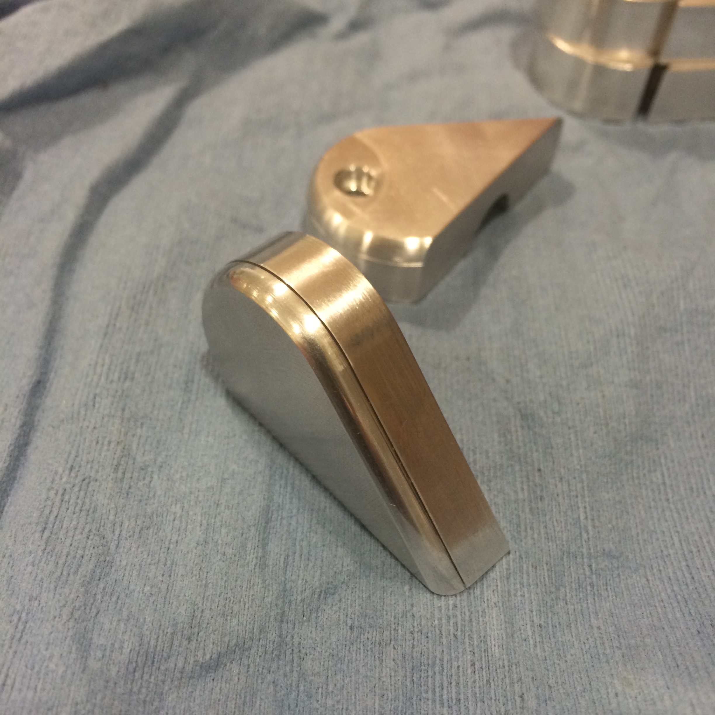
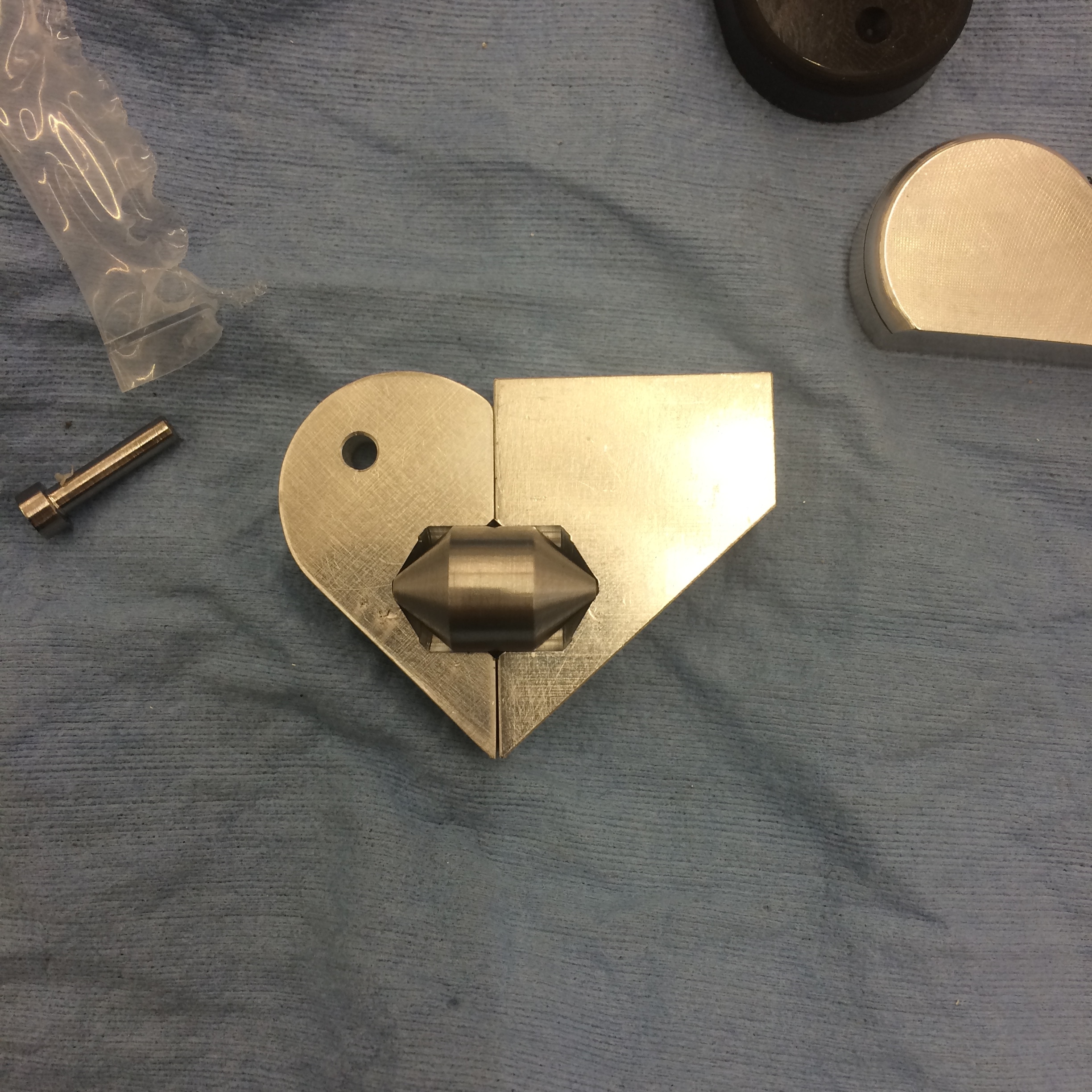
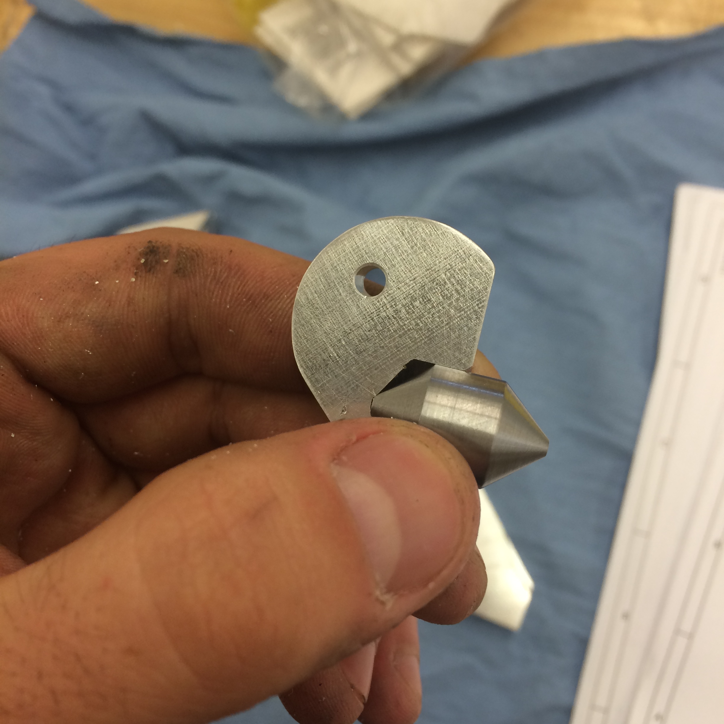
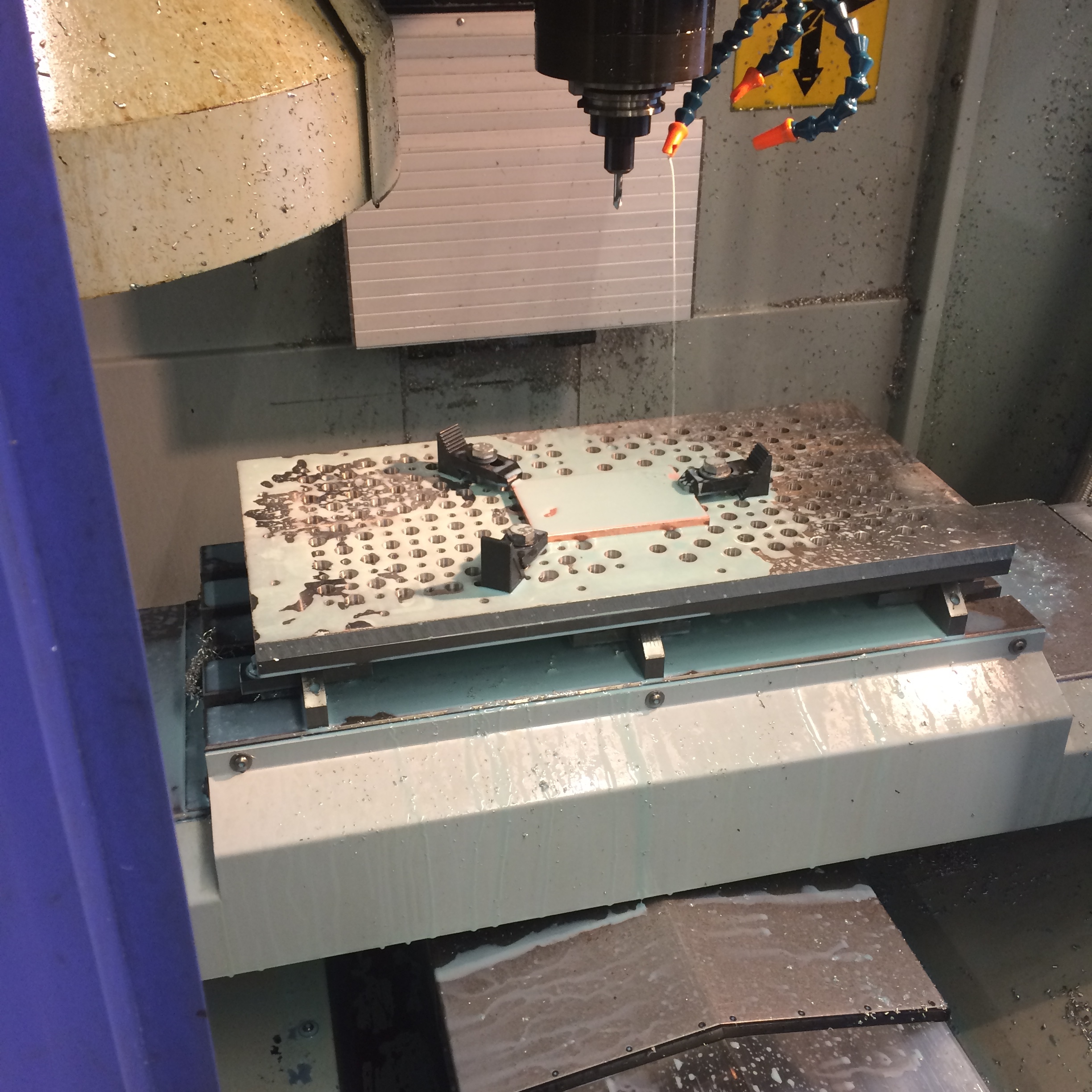
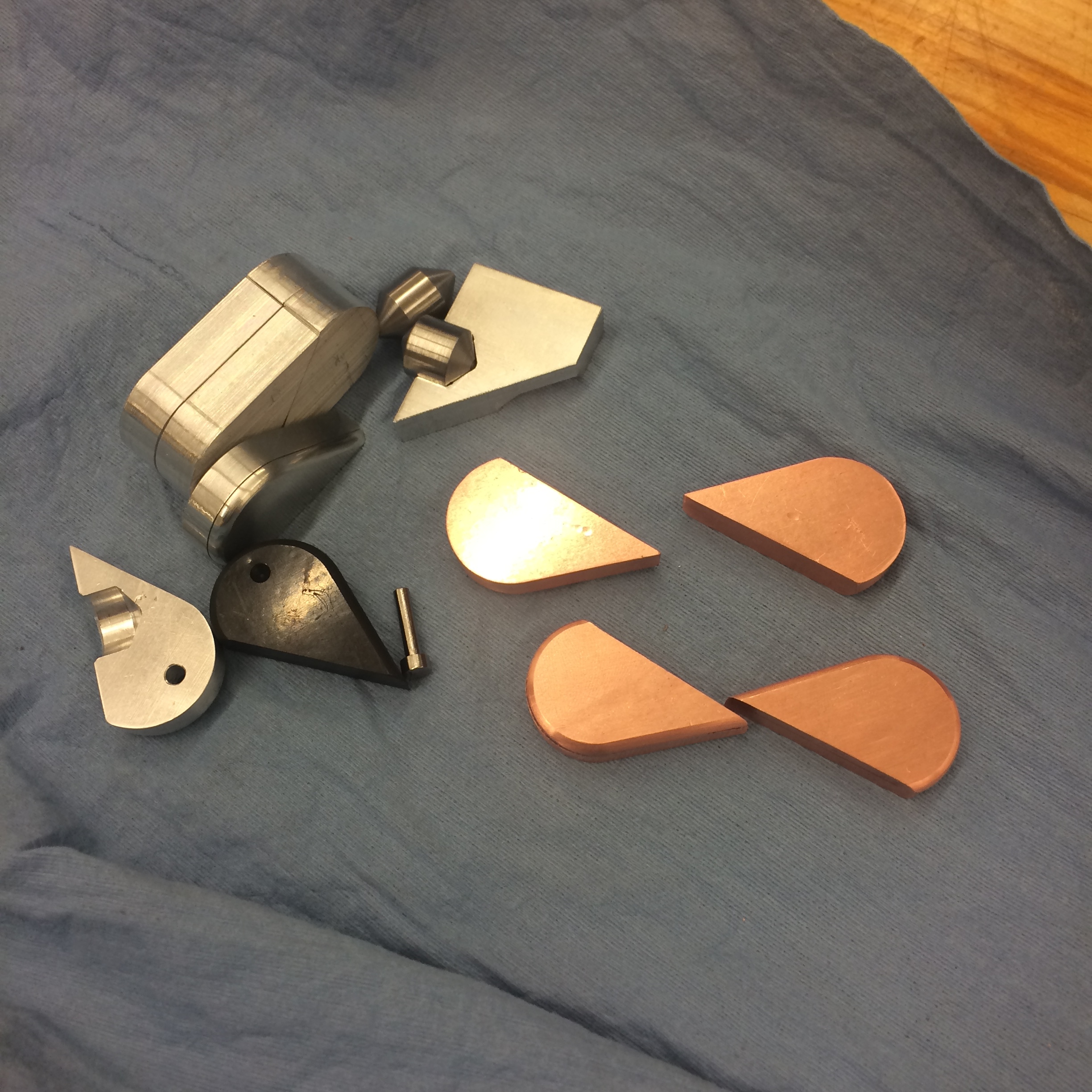
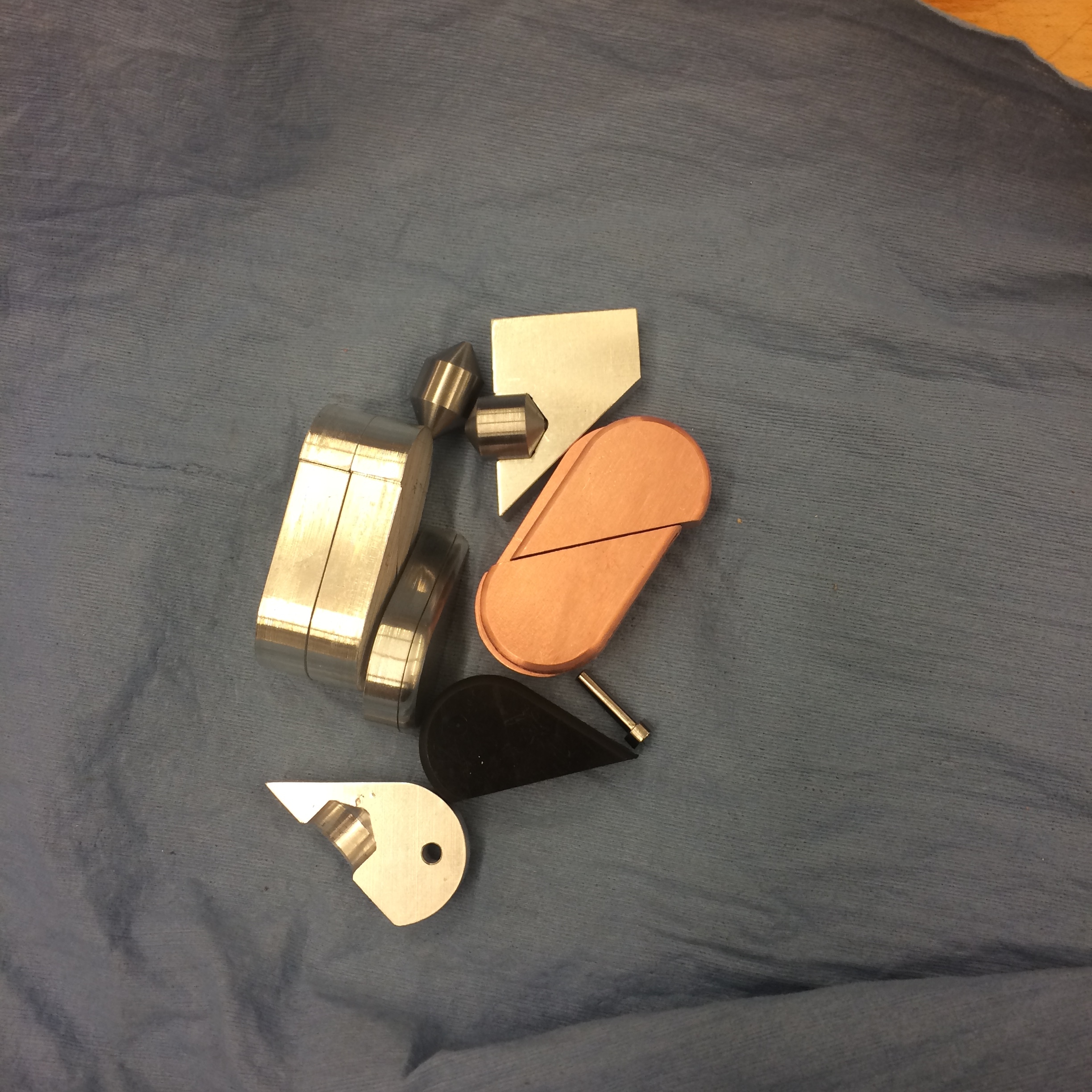
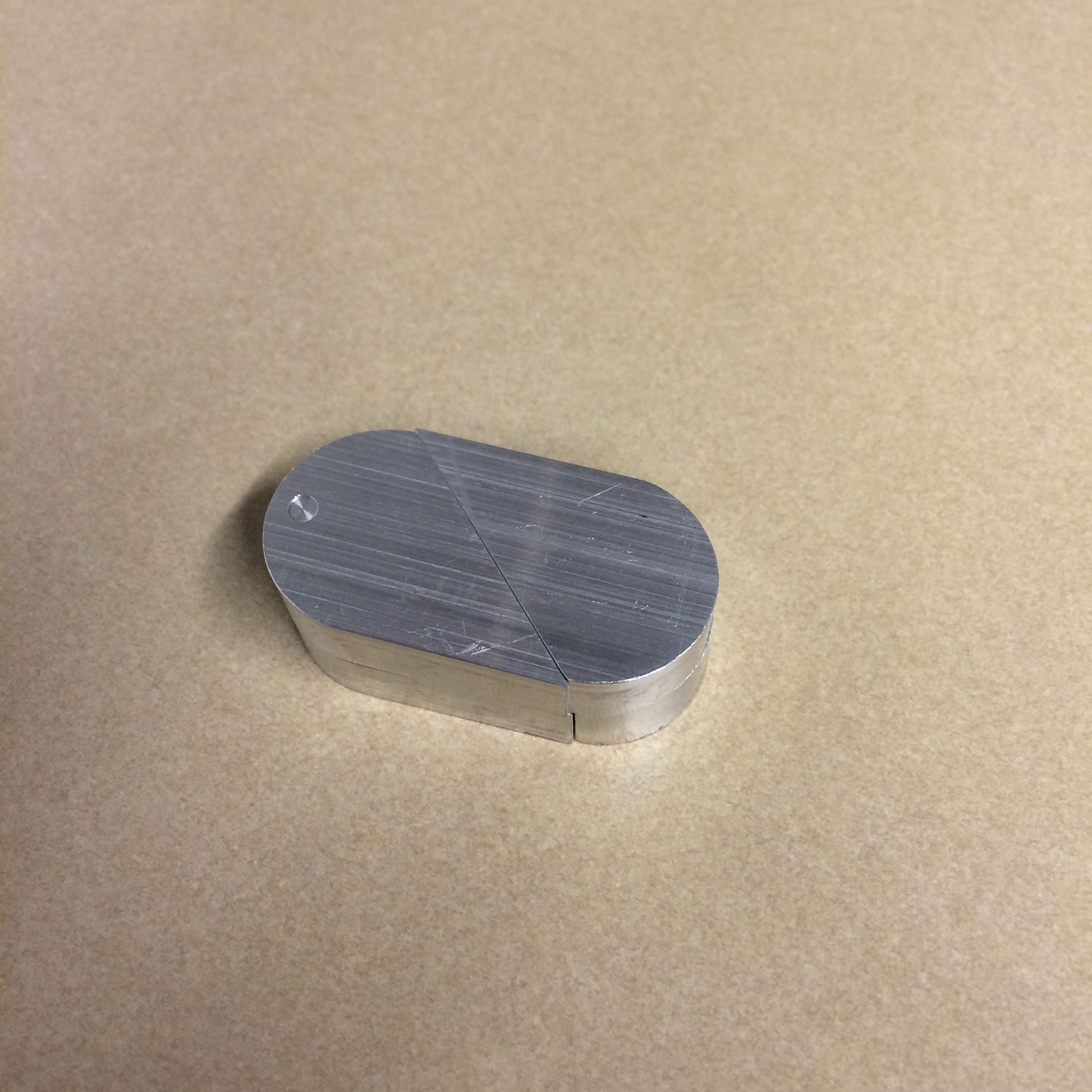
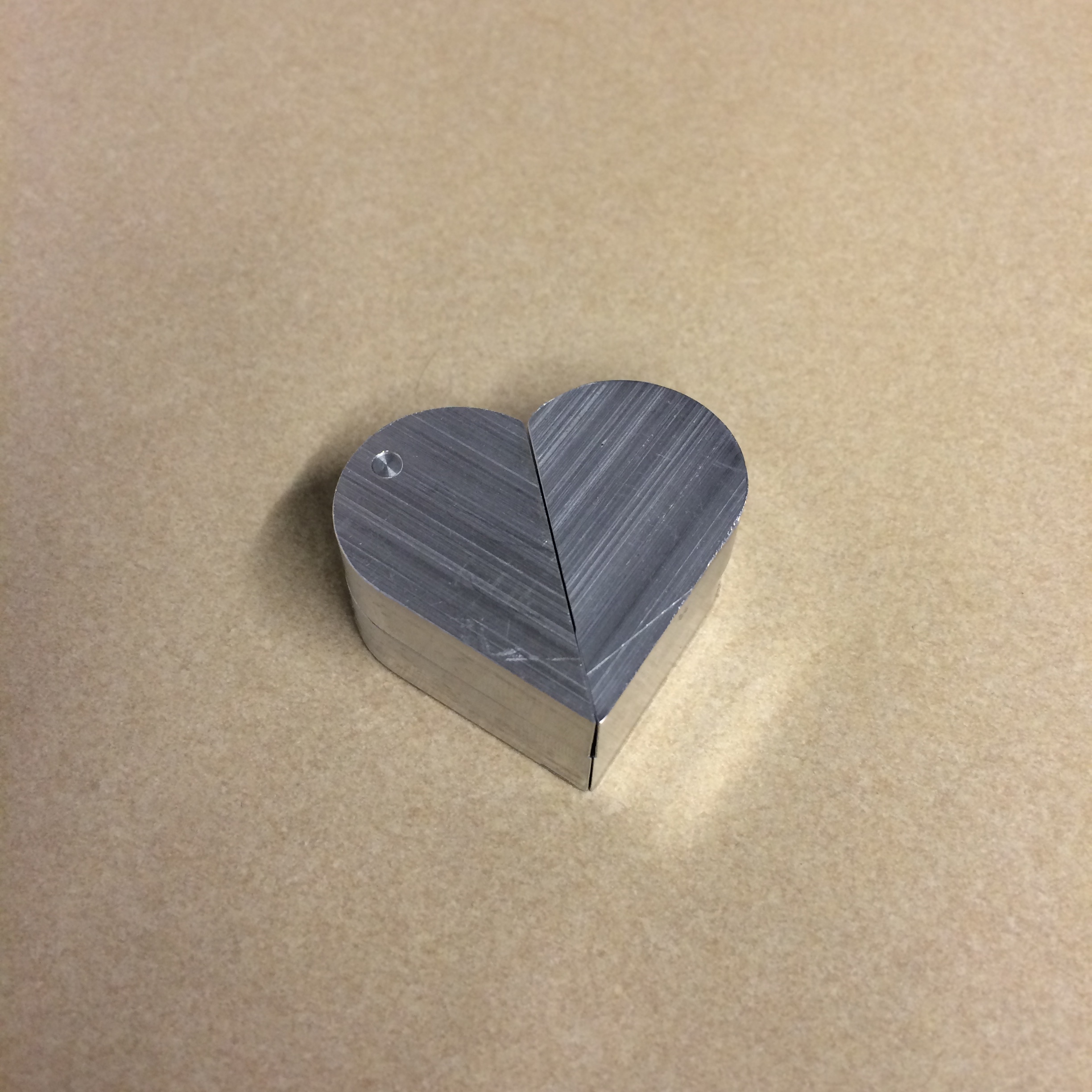
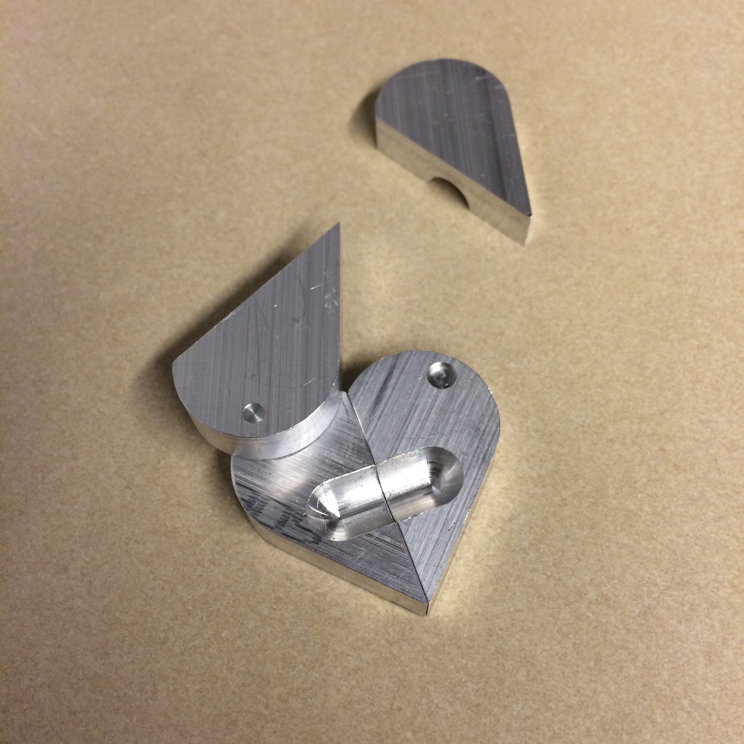
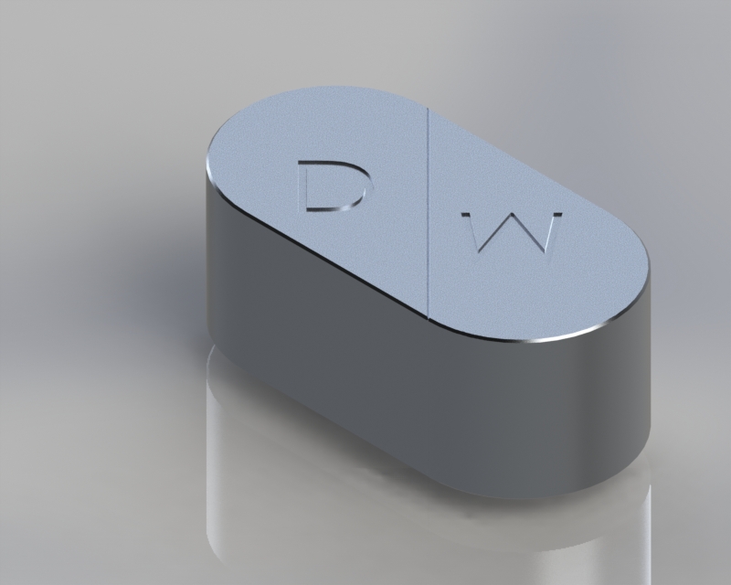
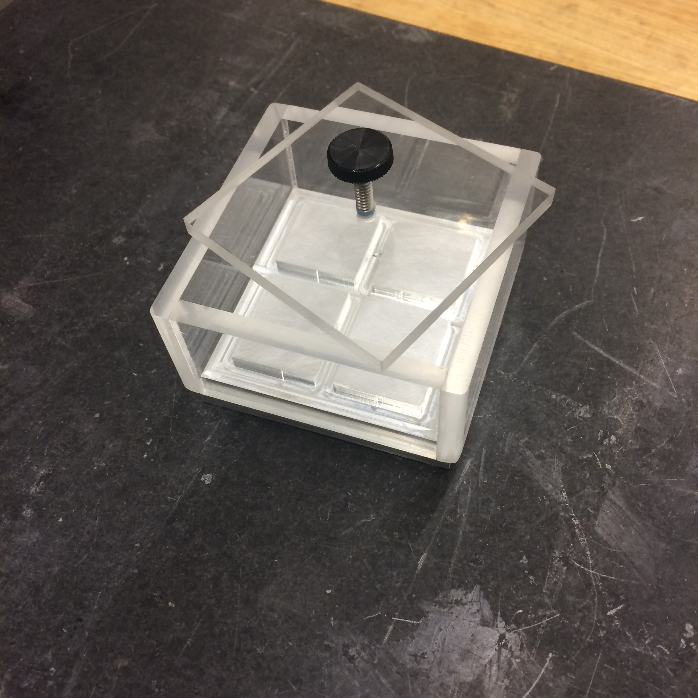
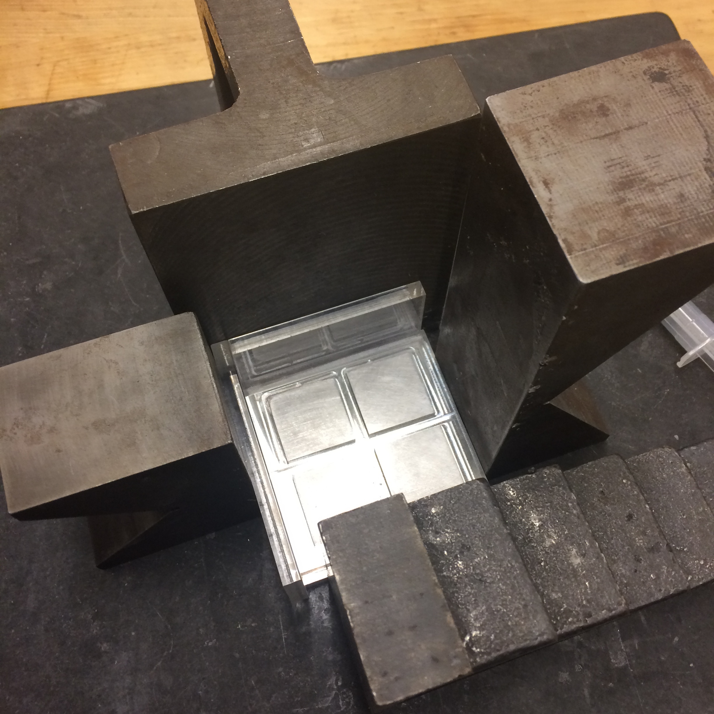
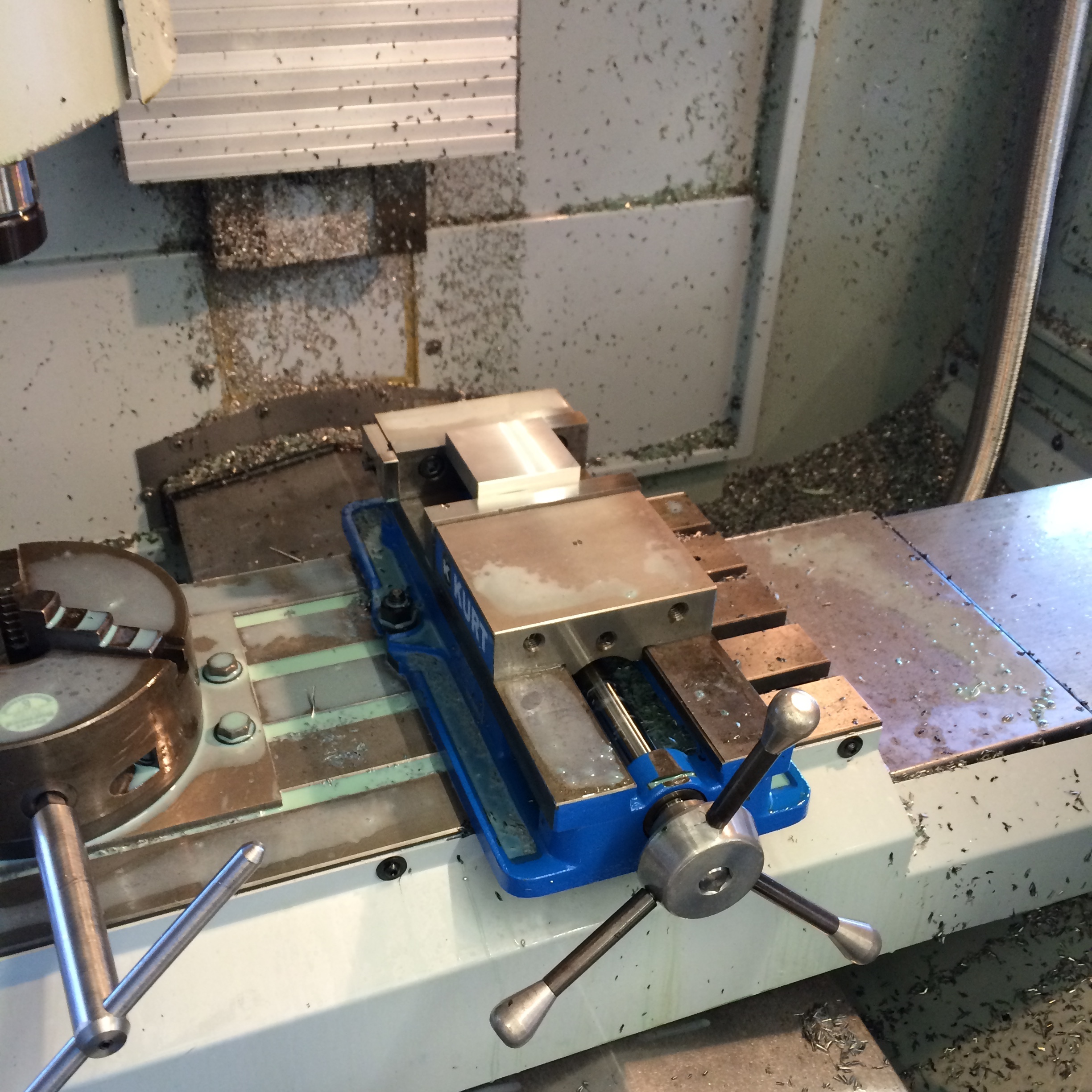
I milled the positive for the mold out of aluminum. I then lasercut some acrylic to form a cavity around the positive in which to cast the mold media which will become the negative. The result will be a simple open faced mold. If the results from this mold are no good, we may try a 2 part mold, but I think a 2 part mold would be overkill for this part. 

Up Next:

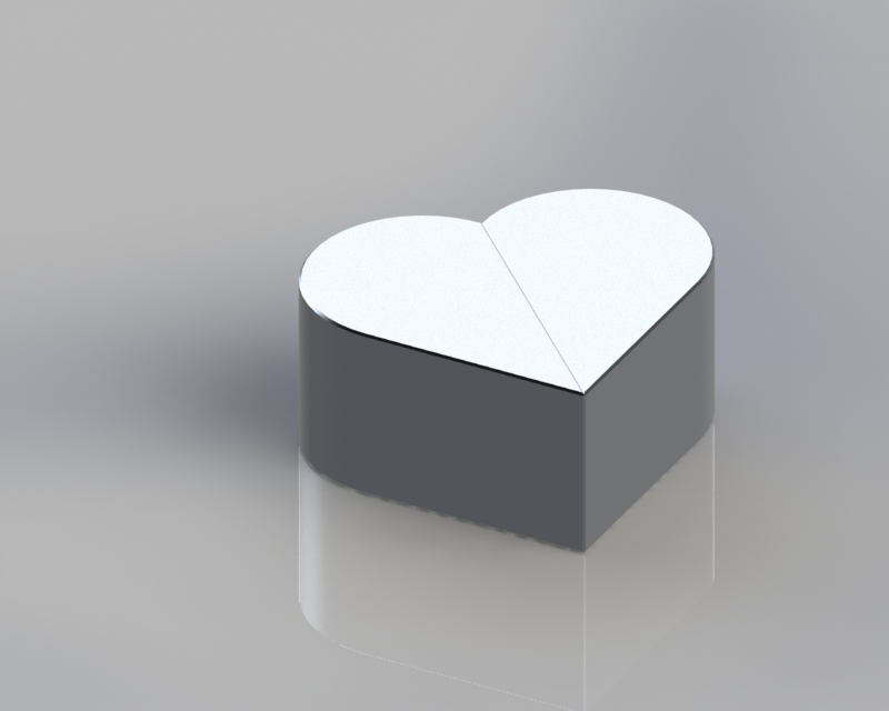
  1. I have a design for the box, but I need to make sure it can be made with an efficient use of materials, and easy to assemble, as we will be making many of these devices.

  2. I need to further embody the electrical design by selecting a UV source. I am having trouble designing a UV LED array that meets the light intensity requirements to activate the QDs while being at a reasonable cost. The UV LEDs are quite expensive, and I'd need a lot of them. I'm considering reverting to a fluorescent source if it turns out to be cheaper.

$\setCounter{0}$
In Engineering Education, Machining Projects Tags Quantum Dots, Design, Molding, Casting, Machining, CNC
Comment
 Checking the dimension of the pin head. Right on the money.

Checking the dimension of the pin head. Right on the money.

 The completed pin.

The completed pin.

IMG_7234.jpg
 Measurements of the corner rounding tool for GibbsCAM.

Measurements of the corner rounding tool for GibbsCAM.

 Testing the corner rounding operation on aluminum. It came out pretty well!

Testing the corner rounding operation on aluminum. It came out pretty well!

 Testing the barrel hole drilling operation.

Testing the barrel hole drilling operation.

 Reaming the hole.

Reaming the hole.

 Chamfering the hole.

Chamfering the hole.

 The barrel hole, complete. Much better finish than with the ball mill.

The barrel hole, complete. Much better finish than with the ball mill.

IMG_7248.jpg
IMG_7252.jpg
 Counterbored hole for the head of the pin.

Counterbored hole for the head of the pin.

 You can see a slight step from the corner rounding tool. I kind of like the way it looks though.

You can see a slight step from the corner rounding tool. I kind of like the way it looks though.

IMG_7263.jpg
 Turning the tapered barrel to match the twist drill angle. But I got the angle wrong...

Turning the tapered barrel to match the twist drill angle. But I got the angle wrong...

 Ready to machine the final product with copper. 

Ready to machine the final product with copper. 

IMG_7266.jpg
 The results! Along with all the other various prototypes I made.

The results! Along with all the other various prototypes I made.

 Checking the dimension of the pin head. Right on the money.  The completed pin. IMG_7234.jpg  Measurements of the corner rounding tool for GibbsCAM.  Testing the corner rounding operation on aluminum. It came out pretty well!  Testing the barrel hole drilling operation.  Reaming the hole.  Chamfering the hole.  The barrel hole, complete. Much better finish than with the ball mill. IMG_7248.jpg IMG_7252.jpg  Counterbored hole for the head of the pin.  You can see a slight step from the corner rounding tool. I kind of like the way it looks though. IMG_7263.jpg  Turning the tapered barrel to match the twist drill angle. But I got the angle wrong...  Ready to machine the final product with copper.  IMG_7266.jpg  The results! Along with all the other various prototypes I made.

Illusionist's Locket Pt. 5

March 19, 2016

Quick update or my locket project. The pin is complete, and to spec. I decided to try using a corner rounding tool to give the locket more refined appearance. They are notoriously difficult to setup in the CNC machine, so I did a test run on a plastic part and on 2 aluminum parts to make sure I got it right before machining into my expensive copper. I also tested the drilling operations on the barrel hole. I originally made this feature with a ballnose mill on the CNC, but the finish was very poor and I would have to ream it anyway to improve the finish. So I decided I might as well drill and ream it from the get-go. 

To do this, I simply clamped two pieces together in the vice, using a parallel bar over the top of the vice to keep the faces normal to the axis of the mill spindle. Then I used an edge finder to locate the hole locations and drilled, reamed and countersunk the holes. 

After confirming all of these things could be done, I decided I was ready to begin making the final product from my copper plate. The feeds and speeds for copper are very slow, and it took almost 2 hours just to make these four little parts. The quality of two of the parts was acceptable, however the other two had gouges in them from the .25" end mill. I think that it was caused by two of the parts being mirrors of the other. For some reason, when coming around the parts the other way, the end mill got sucked into the part, causing those gouges. I may need to remake two of those parts. 

$\setCounter{0}$
In Personal Projects, Illusionist's Locket, Machining Projects Tags Machining, CNC
2 Comments
IMG_7073.jpg
IMG_7074.jpg
IMG_7075.jpg
IMG_7076.jpg
IMG_7073.jpg IMG_7074.jpg IMG_7075.jpg IMG_7076.jpg

Illusionist's Locket Pt. 3

February 16, 2016

I machined the first parts of a prototype today. I used a 3/8" ball-mill to get the central channel for the barrel pivot to rest in. I'm trying to see if there is a better way to do this, as the ballmill leaves a circular edge when I'd rather have a flat face. Also, slight errors in the depth of the ballmill correspond to the channel for the barrel not being cylindrical. There are still many improvements to be made!

$\setCounter{0}$
In Personal Projects, Illusionist's Locket, Machining Projects Tags CNC, Machining, SolidWorks
Comment
 Heart configuration. Magnets are attracted to each other, so the configuration is stable.

Heart configuration. Magnets are attracted to each other, so the configuration is stable.

 Rotating the two halves

Rotating the two halves

 Oval configuration. Magnets now repel each other, so the two halves can easily be pulled apart,

Oval configuration. Magnets now repel each other, so the two halves can easily be pulled apart,

 Disassembly of the two halves reveals hidden pocket for a ring, note, etc.

Disassembly of the two halves reveals hidden pocket for a ring, note, etc.

 "MD" Side

"MD" Side

 "DM" Side

"DM" Side

 In the oval configuration.

In the oval configuration.

 Heart configuration. Magnets are attracted to each other, so the configuration is stable.  Rotating the two halves  Oval configuration. Magnets now repel each other, so the two halves can easily be pulled apart,  Disassembly of the two halves reveals hidden pocket for a ring, note, etc.  "MD" Side  "DM" Side  In the oval configuration.

Illusionist's Locket

February 9, 2016

This is a present I plan on making for my girlfriend for Valentine's Day. It is a metal heart made of two halves that are connected with a dowel pin and magnets. When the two halves are arranged in the heart configuration, the magnets attract each other and so the configuration is stable. When you twist the halves apart, the halves take the form of an oval. With the magnets' positions switched, the halves repel each other, allowing the user to separate the halves and gain access to the secret pockets inside each half. The secret pockets can be used to small rings, a small note, etc.

I've also decided to take advantage of the fact that our initials form a palindrome. If our initials are engraved a certain way on the two halves, on one side of the heart configuration the letters read "MD" (her initials) and on the other side the initials read "DM" (my initials). When rotated to the oval configuration, both sides are the same but are upside down relative to each other. So it reads "DM" or "MD" depending on how you look at it. I like to think of it as being symbolic of our partnership together.

Manufacturing should be relatively simple. The two halves can be CNC'd out of bar stock. I made the angle on each half 45 deg so that any standard shop gauge block could be used to mount the middle face parallel to the table of the mill for drilling the holes and milling the slot. I plan to use a 1/8" steel dowel pin for the center pivot shaft which can be turned on the lathe. Adhesive backed neodymium magnets will be used for retention. If I decide to do the engraving I will need to make some sort of fixture or jig for a flip milling operation on the reverse side of each half of the heart. Hopefully I can make a simple jig with some locating pins mounted on the mill table.

Note: This design is inspired by an Instructable I remembered seeing a while back. The author of the Instructable credits the design to a scene from the movie "The Illusionist". As you can see, the locket in the movie has 2 additional hinges that allow the locket to swing open in both the oval and heart configuration. The "illusion" is that when you open the locket in one configuration, one person's image appears. But when you open the locket in the other configuration, the other person's image appears. And the baffling thing is, it's hard to understand how twisting the locket from the heart to the oval configuration doesn't rip the picture in half. This is a *greatly* simplified version where there really is no illusion. I will use this design as a starting point and hopefully be able to design a locket that has the full functionality as seen in the movie.

$\setCounter{0}$
In Personal Projects, Illusionist's Locket, Machining Projects Tags Machining, CNC, SolidWorks, CAD
Comment

Blogpost Search

Blogposts by Category

Select Category
  • Academic Projects
  • Aviation
  • BreakerBot
  • Engineering Education
  • Illusionist's Locket
  • MATLAB Projects
  • Machining Projects
  • Personal Projects

Archive

  • May 2024
  • December 2019
  • November 2019
  • September 2019
  • April 2017
  • January 2017
  • August 2016
  • May 2016
  • April 2016
  • March 2016
  • February 2016
  • January 2016
  • November 2015
  • October 2015
  • June 2015
  • April 2015
  • February 2015
  • January 2015

Copyright © David Miller 2019