New Project: Quantum Dot Lite Brite

My boss put me on a team to design and fabricate the hardware required for a new activity being developed. The activity is centered on Quantum Dot (QD) technology. The basic concept is that these nano-scale QDs emit single wavelengths of light when excited by UV light. The emitted wavelength is related to the radius of the QD, so larger QDs emit longer wavelengths. Typically, QDs are stored in a liquid solution which is toxic and dangerous for children to handle. However, it is possible to embed QDs in a plastic polymer which is safe for children to handle. The plastic is made by creating a solution of QDs in the polymer, pouring the solution into a mold, and vacuum baking the solution to harden the plastic in the mold.

The plastic itself is clear until you illuminate it with UV light. Once illuminated with UV light, the QDs inside the plastic will emit light, causing the plastic to glow! We plan on making lots of plastic pieces with different sized QDs in them (the QD sizes will correspond to different colors) and having students arrange the plastic pieces on a grid to make a picture of something. These plastic pieces will essentially be pixels in that sense. They will insert their arrangement of pixels into a UV light-box consisting of of a UV source, a UV transparent platform to lay the arrangement on, and a UV resistant shield for viewing the glowing arrangement. 

There are three issues I have identified as being critical to the success of the project:

  1. Safety. We need to ensure that the children cannot activate the UV source while the UV shield is not installed, to be sure that the children will not be exposed to the UV rays. We also need to assess the effectiveness of the UV shield.

  2. Light Source Requirements. We need to ensure that our light source emits UV light at the correct wavelength to excite the QDs, and that the intensity of the UV rays is high enough that the pixel arrangement will glow visibly and impressively to the students. We are currently leaning towards using an array of UV LEDs underneath the arrangement to ensure all the pixels receive an equal light intensity.

  3. Casting the Pixels. Currently the pixels are cast in an off the shelf silicone mold used for baking. The plastic parts from the mold are roughly rectangular, but have many imperfections and low dimensional repeatability. We need to develop a mold/molding process that results in repeatable, rectangular plastic pieces that will fit together on a grid. Fitting together multiple pieces in a grid will result in a tolerance stackup. So the smaller we decide to make the pixels, the more we can fit in the grid, and therefore the tighter the tolerance on each pixel will have to be to guarantee the same degree of alignment on the grid.

Wind Turbine Analysis

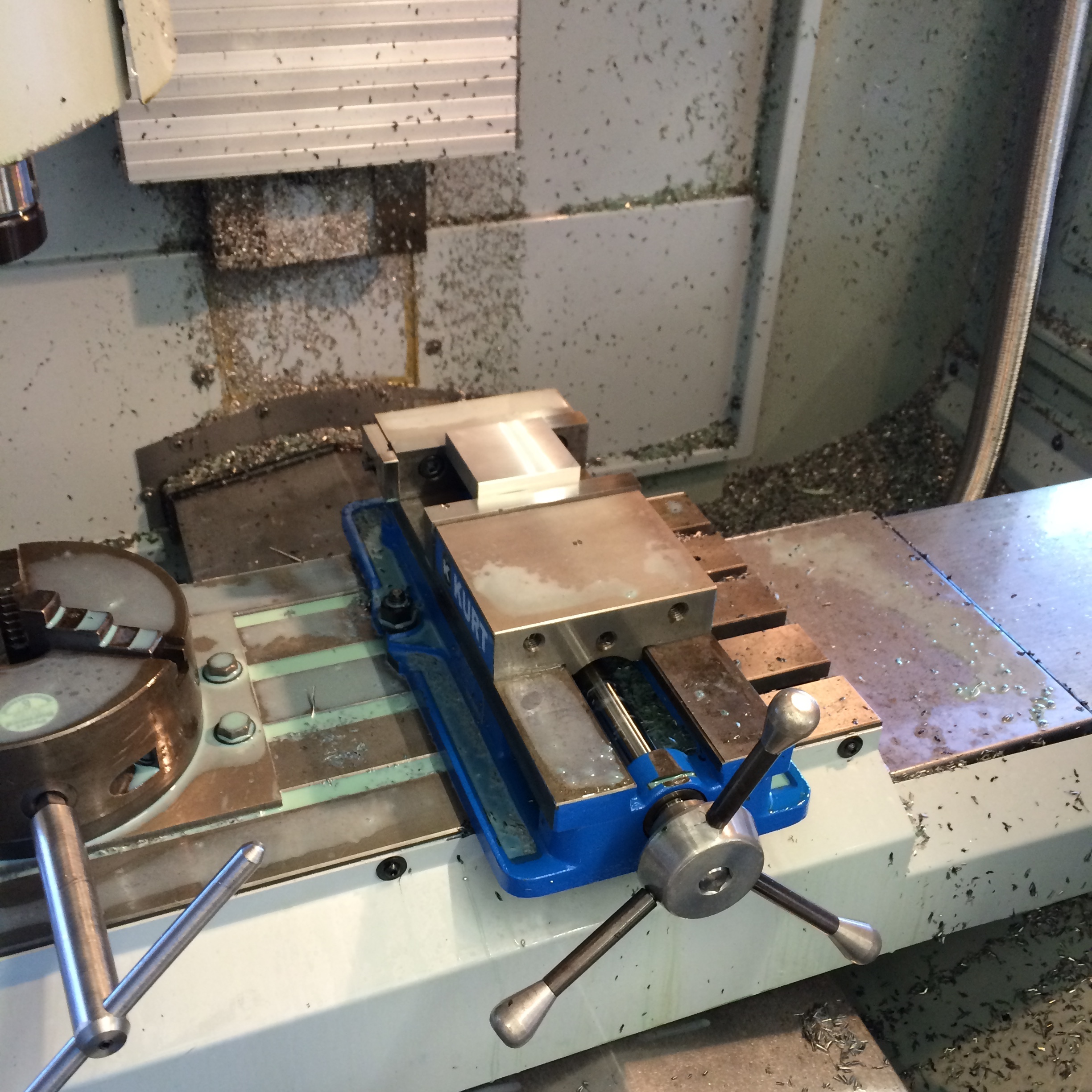
One of my tasks as an engineering education developer at BU is to beef up the content of some activities with some higher level concepts. Recently I've been working on an activity where students get to design, build, and test their own wind turbines. Right now the activity works great with middle school students, but we want to improve the activity and make it more challenging so that we can bring it to high schools as well. The activity uses store bought wind turbine kits with a variety of blade types. Students can choose the material of the blades, the size of the blades, how many blades, and how to angle the blades. Then, once they've built their turbine, it's placed in front of a box fan and connected to a volt meter to measure the power. After their first design, students are allowed to make changes and test a second time before the teacher gathers everyone for a recap. 

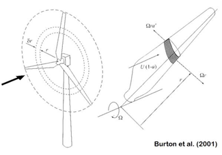
Our goal is to enable students to use data obtained from their first test to quantitatively evaluate and improve the performance of their design. This requires some type of quantitative analysis of the wind turbine. So I began doing some math. I just finished a course in aerodynamics, where we learned all about airfoils and wings, so I felt I had a good handle on the concepts at hand. After all, a wind turbine is just a bunch of rotating wings, right?

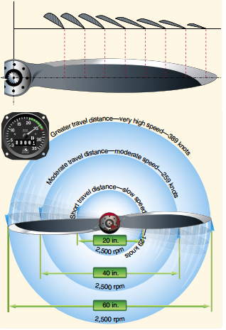
Well regardless, that's how I modeled it. But unlike regular airplane wings, rotating wings (aka blades) don't all feel the same wind. The ends of the blades travel much faster than the inward portions, meaning the airspeed for that section of blade is faster. So the normal approach doesn't work in this case, because the wind is quite different everywhere across the wing. 

This image shows how much the actual speed of the blade varies with distance from the hub. Image Credit: http://www.cfinotebook.net/notebook/operation-of-aircraft-systems/propeller.php

This image shows how much the actual speed of the blade varies with distance from the hub. Image Credit: http://www.cfinotebook.net/notebook/operation-of-aircraft-systems/propeller.php

So what can be done to solve the problem? Well when engineers come across a problem like this, they usually try to reduce it to something they already know how to solve. To give an example of how this is done, imagine taking a thin slice of the blade. Because it is so thin, the wind speed on one end is almost the same as the wind speed on the other end. Because the wind speed is *essentially* the same all across this tiny wing, we can use our original method on this tiny wing and get a good approximation. And it turns out if you add up an infinitely large number of infinitely thin blades, you can actually end up with a complete, finite blade; and no error! This technique of adding radial sections of the blade is called the Blade Element Method (BEM). 

Here is a picture showing the 'slice' of the blade. Image Credit: http://fessrg.ucsd.edu/Research/Wind/

Here is a picture showing the 'slice' of the blade. Image Credit: http://fessrg.ucsd.edu/Research/Wind/

BEM seems to be pretty widely used for getting preliminary performance estimates when designing a new propeller, helicopter rotor, wind turbine, or really anything else that has rotating wings. However there are limitations. The most significant limitation is that BEM cannot account for any radial flow - that is, if there is air moving along the blade from one tiny wing to the next. When engineers are satisfied with results from preliminary estimates such as BEM, they may move on to more accurate and sophisticated methods like a numerical simulation. But for my purpose, I think BEM is just fine.