• Portfolio
  • Aviation
  • Blog
  • About
Menu

David S Miller

  • Portfolio
  • Aviation
  • Blog
  • About
 The ConEd building is a historical landmark so the exterior masonry, etc. cannot be modified.

The ConEd building is a historical landmark so the exterior masonry, etc. cannot be modified.

 The interior is very modern, however.

The interior is very modern, however.

 BreakerBot sits on a sofa in the lobby.

BreakerBot sits on a sofa in the lobby.

 Setting up in the conference room

Setting up in the conference room

 Group photo after the presentation.

Group photo after the presentation.

 The ConEd building is a historical landmark so the exterior masonry, etc. cannot be modified.  The interior is very modern, however.  BreakerBot sits on a sofa in the lobby.  Setting up in the conference room  Group photo after the presentation.

BreakerBot Moves to ConEdison

May 25, 2016

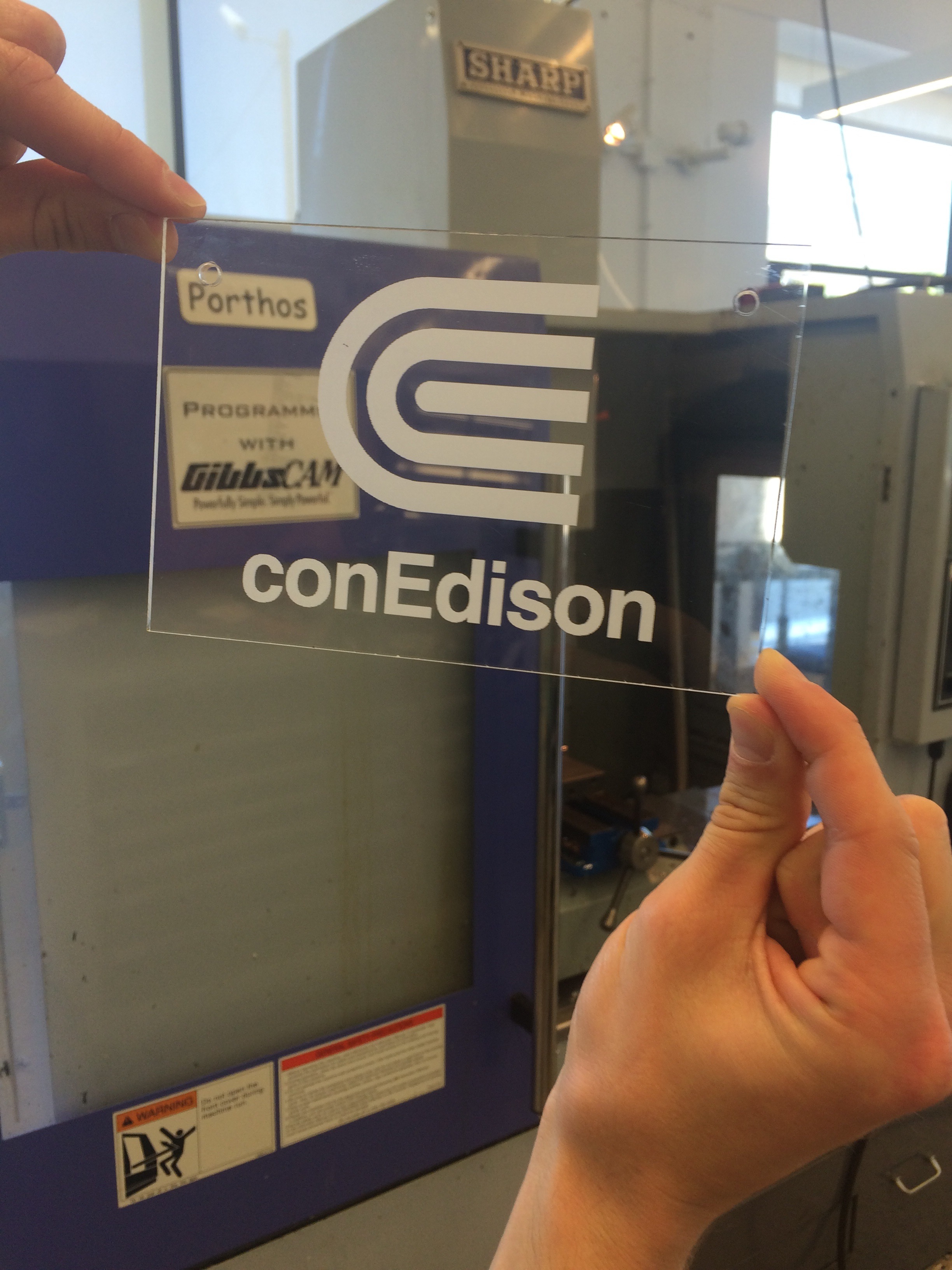
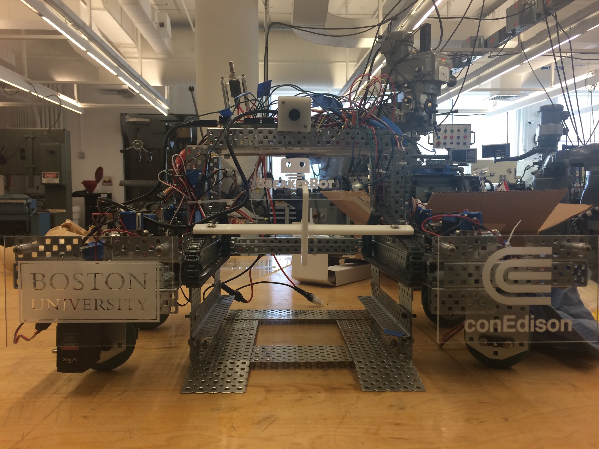
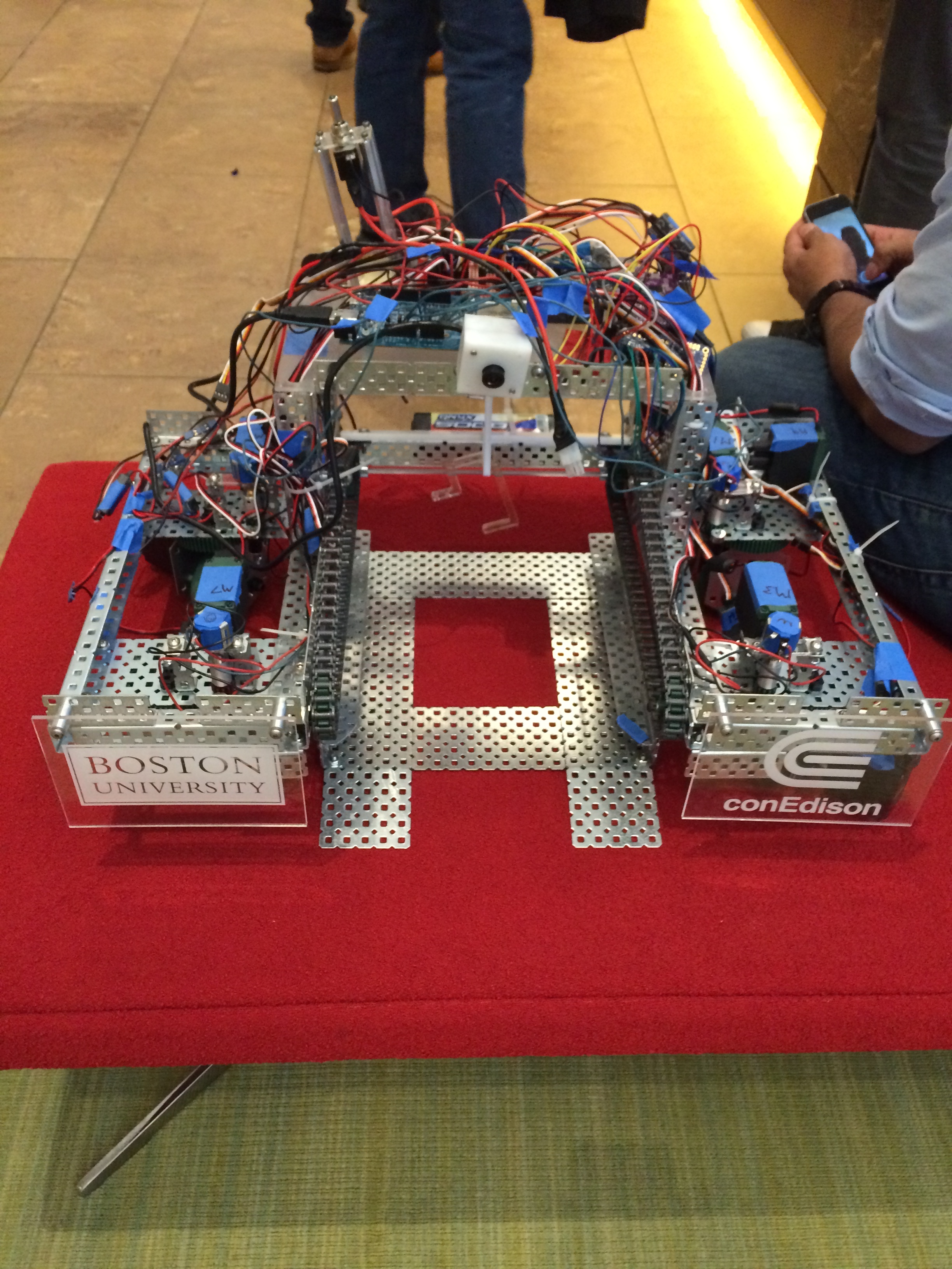
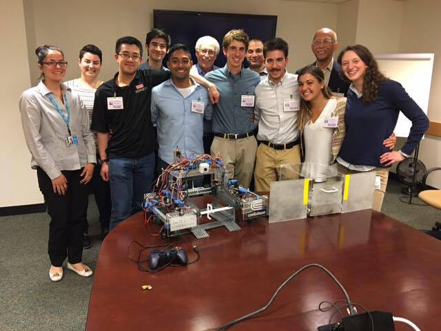
Yesterday we visited ConEdison in my hometown of NYC to present our Senior Capstone project, BreakerBot. The goal of this phase of the project was to convince ConEd to continue future phases of the project at BU by delivering a prototype that could:

  1. Automatically align to the front of the cubicle where the breaker is located

  2. Automatically remove the breaker from the cubicle and reinsert it once aligned

We demonstrated these functions for them with our prototype, and we had a long conversation about the technical and logistical constraints that would need to be considered and accounted for in a full scale robot. As for sealing ConEd's commitment for next year, we are still working on the business aspect of the deal and that's really all I can say right now. 

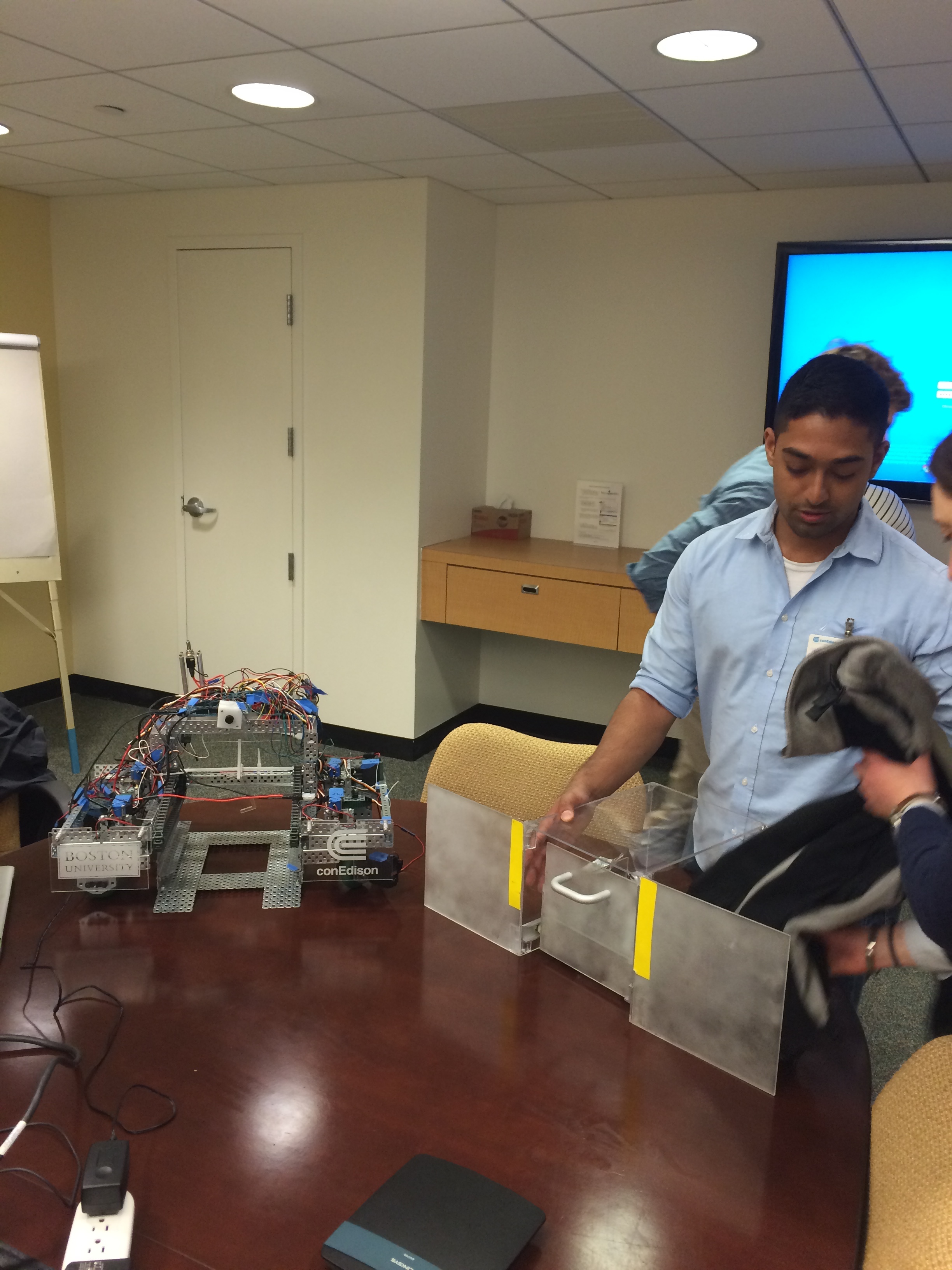
We did leave BreakerBot there so that it could be used to help secure funding for the project from the higher-ups who were unable to attend our presentation. It was hard to say goodbye to BreakerBot, but we are very happy to know that BreakerBot has a new home at ConEd. 

$\setCounter{0}$
In Academic Projects, BreakerBot Tags BreakerBot
Comment
 Always use vector image formats (PNG, TIF, etc.) to ensure crisp resolution at any scale.

Always use vector image formats (PNG, TIF, etc.) to ensure crisp resolution at any scale.

 Aluminum standoff spacers

Aluminum standoff spacers

 They have an additional function to prevent the swerve modules from crashing into the plaque when the robot steers...

They have an additional function to prevent the swerve modules from crashing into the plaque when the robot steers...

 BreakerBot looking good! We have to do something about its hair though

BreakerBot looking good! We have to do something about its hair though

 Always use vector image formats (PNG, TIF, etc.) to ensure crisp resolution at any scale.  Aluminum standoff spacers  They have an additional function to prevent the swerve modules from crashing into the plaque when the robot steers...  BreakerBot looking good! We have to do something about its hair though

BreakerBot Gets a New Look

May 11, 2016

Even though our senior design class is technically over, we still have some things to finish with our project. We are traveling to my hometown of New York City to give a presentation and demonstration of our robot at ConEd. The goal of this is to convince them to continue future phases of the project at BU to design and build a full scale version of the robot. 

We spent the day trying to make our robot look a bit more professional and presentable by adding lasercut acrylic plaques of our sponsors' logos. We also turned some aluminum standoff spacers that I think add a really nice touch.

$\setCounter{0}$
In Academic Projects, BreakerBot, Machining Projects Tags BreakerBot, Lasercutting, Machining
Comment
rstick_x-right_lstick_k-right_position-trace.png
lstick_y-up_lstick_k-right_position-trace.png
lstick_y-up_rstick_x-right_position-trace.png
lstick_y-up_position-trace.png
lstick_y-up_rstick_x-right_lstick_k-right_position-trace.png
pure_rotation.png
rstick_x-right_lstick_k-right_position-trace.png lstick_y-up_lstick_k-right_position-trace.png lstick_y-up_rstick_x-right_position-trace.png lstick_y-up_position-trace.png lstick_y-up_rstick_x-right_lstick_k-right_position-trace.png pure_rotation.png

Kinematics of Wheeled Mobile Robots Pt. 2

February 29, 2016

I discovered a few minor issues with my previous derivation. I had not converted the unit vectors from one frame to the other correctly, and I left some of the expressions in the unit vectors of an inappropriate frame. MATLAB was used to verify the equations. Simple inputs were sent to the equations and various outputs were plotted for evaluation. The rainbow plots show the physical path of the robot in the XY plane. The color indicates the angle of rotation in degrees. The last graph shows my original eureka moment when I finally realized I fixed the problem. Previously, there was a cusp in the magnitude of velocity when it should have been constant. When I saw the constant red line, I knew I was on the right track. 

Because the control inputs are centered to the robot's frame, if you hold constant translational inputs with a rotation, the robot will end up taking a curved path. However if you hold constant translational inputs with no rotation, the robot will travel straight. This is shown by the graphs with no color change.

$\setCounter{0}$
In BreakerBot, MATLAB Projects Tags robotics, kinematics, BreakerBot, MATLAB
Comment
 Reference frames.

Reference frames.

 Robot reference frame showing wheel locations and wheel angle.

Robot reference frame showing wheel locations and wheel angle.

 Coordinate frame transformation yields wheel velocities required to achieve specified motion.

Coordinate frame transformation yields wheel velocities required to achieve specified motion.

 Wheel rotational speeds and steering angles can be determined from the wheel velocity vectors.

Wheel rotational speeds and steering angles can be determined from the wheel velocity vectors.

 Position vectors from the center of the robot to each of the four wheels.

Position vectors from the center of the robot to each of the four wheels.

 Reference frames.  Robot reference frame showing wheel locations and wheel angle.  Coordinate frame transformation yields wheel velocities required to achieve specified motion.  Wheel rotational speeds and steering angles can be determined from the wheel velocity vectors.  Position vectors from the center of the robot to each of the four wheels.

Kinematics of Wheeled Mobile Robots

February 2, 2016

After many discussions, our group has decided that four-wheel drive simply does not permit adequate control of the robot for aligning with the circuit breaker cubicle. So we are reverting to our original drive train choice: swerve drive. Swerve drive is a holonomic locomotion system in which each wheel can pivot about its own vertical axis. Using a swerve drive, the robot will strafe sideways along the face of the circuit breaker cubicle, detecting the edges of the cubicle and using those edges to laterally align the robot. Then, the robot will perform an angular alignment to the face of the cubicle, and advance forward to extract the breaker. The angular alignment and subsequent forward motion would not have been possible with a four-wheel drive system; as the translation and rotation of the robot are coupled.

I derived the inverse kinematics of the robot for our computer engineers to use in their control algorithms. The derivation is quite simple mathematically, but it can easily get confusing to understand from a physical sense. I like to imagine what I would experience if I were sitting on the different points where the wheels are located on the robot. This helps me to see why certain terms are in the resulting equations and verify if the results make sense. 

PDF derivation of the kinematics.


$\setCounter{0}$
In BreakerBot, MATLAB Projects Tags robotics, kinematics, BreakerBot
Comment
 Rendering of the detailed assembly. Bearings and fasteners have been specced.

Rendering of the detailed assembly. Bearings and fasteners have been specced.

image1.png
image3.png
image.png
image4.png
 Rendering of the detailed assembly. Bearings and fasteners have been specced. image1.png image3.png image.png image4.png

Omniwheel Design

January 12, 2016

Currently working on a high load capacity omniwheel design for our circuit breaker removal robot (BreakerBot). Off the shelf omniwheels of this load capacity (750lb) are very expensive! This design is an exercise to see if constructing our own wheels is a feasible solution. Our other options are to choose an alternative drive train system that doesn't require these expensive and complex omniwheels. However, those systems are either non-holonomic (ackerman steering) or even more complex (swerve drive). I am hoping that we will be able to use these wheels with sort of H-drive system. We do not need full holonomic control, but the ability to strafe and turn on a point would be very useful for aligning the robot with the breaker's cubicle for extraction. 

$\setCounter{0}$
In BreakerBot Tags robotics, omniwheel, BreakerBot, Design, SolidWorks
Comment

Blogpost Search

Blogposts by Category

Select Category
  • Academic Projects
  • Aviation
  • BreakerBot
  • Engineering Education
  • Illusionist's Locket
  • MATLAB Projects
  • Machining Projects
  • Personal Projects

Archive

  • May 2024
  • December 2019
  • November 2019
  • September 2019
  • April 2017
  • January 2017
  • August 2016
  • May 2016
  • April 2016
  • March 2016
  • February 2016
  • January 2016
  • November 2015
  • October 2015
  • June 2015
  • April 2015
  • February 2015
  • January 2015

Copyright © David Miller 2019