
For our senior design project, we are trying to implement a swerve drive system to achieve holonomic robot motion. None of us really know much about controls, but from the information we have gathered online, it seems advantageous to model our control system in Simulink before trying to implement it with code on our robot. Simulink seems pretty simple to use, at least for basic PID loops. If you have a block diagram for the system you want to model, you just drag and drop the blocks of the system and connect them together. You can change the parameters of the blocks simply by double clicking.
I made a really simple one here of a basic PI loop responding to a step input. You can change the proportional and integral gains to tune the controller, if you wish.
Here are my concerns regarding the Simulink model:
I don't know how to model my inverse kinematics with the standard blocks. Will I have to make my own custom block to do all the kinematics, or make each step of the equation a separate block?
How to get the angle of the robot with respect to the ground? In our robot, this will come from a gyro, but how can I model this in Simulink?
Step inputs and sinusoid inputs are useful, but it would be really helpful to model the input from our actual joystick. I need to figure out how to do that. There is a joystick block, but I have no idea how to use it.
We currently have no idea how to model the robot dynamics (the 'plant', in control theory lingo). This is the most important part. If your plant is inaccurate, your control will not work.
Where does the plant begin/end? Should we attempt to model the motor behavior in Simulink? Or make the motor part of the plant? I've found sources online that go either way.
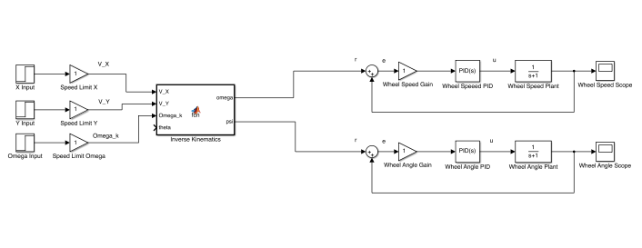
So after a couple hours of playing with Simulink, I think I have solved issue #1. I ended up writing a custom Simulink block from a MATLAB function. It then compiles the MATLAB code into the block. I am making a smaller system to test the kinematics independently. I will check them with the graphs I generated earlier in the semester.
I sort of found a way around #2 for now by integrating the angular rate signal. But the angle from this is before the plant, so it is not really correct. But it may work for now, just to get the system to run.
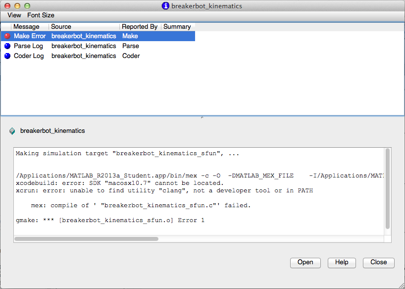
The main problem I have right now is compiling the code from the MATLAB Function Block. The Simulink-compatible C-compiler is was not installed on my computer, so I had to download the Xcode app and use the compiler. But it's still returning an error, so there is something else I have to fix evidently.