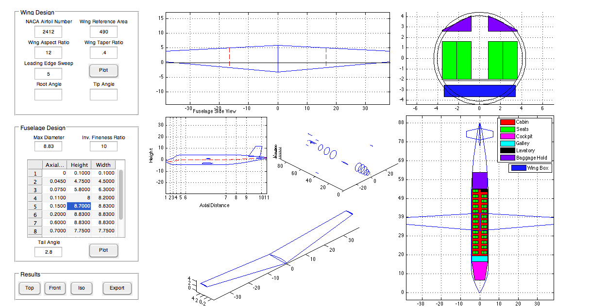
This is the master program which all the functions described in previous posts feed into. This takes inputs from the fuselage designer, wing designer, and empennage designer and puts all the components together. The motivation for this project was to be able to quickly and easily iterate through aircraft designs. All of the performance calculations were done in an excel spreadsheet, but Excel is not good at making custom plots or managing data. This program receives the geometric parameters of the airplane calculated by the Excel sheet, and uses them to 'build' the airplane for visualization and accurate component layout.
The component layout in the spreadsheet does not account for the form of the volume components (passenger cabin, cockpit, galley, wing box, etc.). On more than one occasion we had designed a fuselage that seemed to contain all the components, only to realize that the calculated cabin length was longer than the fuselage of the aircraft! This program was intended to solve that problem by visualizing the components for instantaneous feedback on the quality of the layout.
The other main goal of the program was to facilitate the rapid 3-D modeling of the aircraft. Unlike most other objects undergraduates are used to CADing, aircraft often have complex curvatures and geometries that take a long time to make manually. This program produces curves for the fuselage, main wing, and tail surfaces and positions them according to the design specifications. The coordinates for the curves are then exported as .txt files, which can be uploaded into SolidWorks as curves and lofted together. This drastically reduces the time required to produce a solid model and thus enables more rapid design iteration and evaluation.
I'd like to continue adding more to this program, but it looks like there simply isn't enough room on the UI to add more input boxes. Already, many of the parameters cannot be changed from the UI; the code must be manually altered. I was thinking of adding tabbed panels to increase the number of inputs possible, but from my [limited] research they don't seem to be well supported. I think this version should do for now.

