• Portfolio
  • Aviation
  • Blog
  • About
Menu

David S Miller

  • Portfolio
  • Aviation
  • Blog
  • About
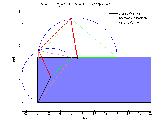
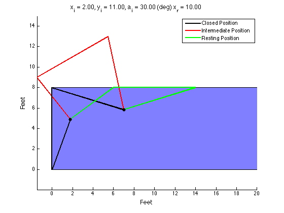
 It appears that this mechanism is valid... But how can I be sure?

It appears that this mechanism is valid... But how can I be sure?

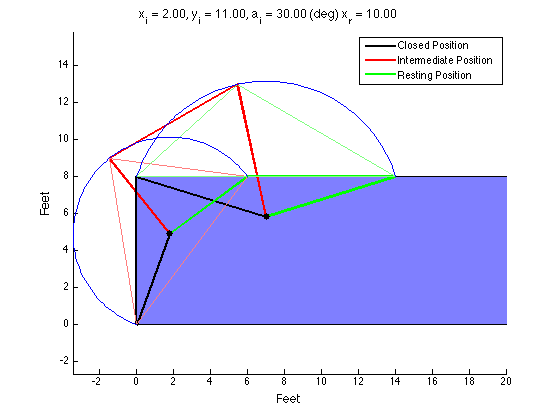
 By plotting arcs around the links I ensure they stay the same size throughout.

By plotting arcs around the links I ensure they stay the same size throughout.

 Here are some varying geometries that achieve the same goal.

Here are some varying geometries that achieve the same goal.

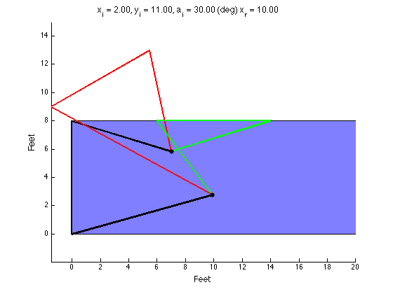
 This is when I was still debugging my code. You can clearly see each member changes length as it rotates, which cannot occur.

This is when I was still debugging my code. You can clearly see each member changes length as it rotates, which cannot occur.

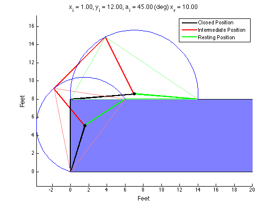
 This geometry resulted in a bearing that was placed off the surface of the shipping container.

This geometry resulted in a bearing that was placed off the surface of the shipping container.

 One more geometry. The next question is, how can you optimize the linkage??

One more geometry. The next question is, how can you optimize the linkage??

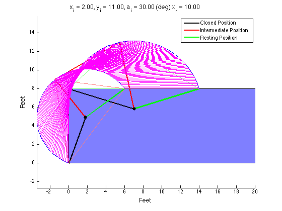
 I tried plotting snapshots of the linkage but it didn't work so well. This is wrong because the magenta snapshots do not align with the red position.

I tried plotting snapshots of the linkage but it didn't work so well. This is wrong because the magenta snapshots do not align with the red position.

 It appears that this mechanism is valid... But how can I be sure?  By plotting arcs around the links I ensure they stay the same size throughout.  Here are some varying geometries that achieve the same goal.  This is when I was still debugging my code. You can clearly see each member changes length as it rotates, which cannot occur.  This geometry resulted in a bearing that was placed off the surface of the shipping container.  One more geometry. The next question is, how can you optimize the linkage??  I tried plotting snapshots of the linkage but it didn't work so well. This is wrong because the magenta snapshots do not align with the red position.

MATLAB Four-Bar Linkage Design

March 24, 2016

The Product Design class I am a TA for had an assignment to design a four-bar mechanism to move a lid on a shipping container up and over so that it rested on the top of the container during loading. There was extra credit awarded to those who could analytically arrive at a design using MATLAB (or some other language). I made my own solution for fun and to check student's solutions. I tried to get it to plot each snapshot (in magenta) but it was not correct and I didn't have time to figure it out. 

So, here's how to design a typical four-bar linkage:

  1. Define the desired locations of your coupler. You define two or three locations you want the coupler to travel through. My code only works with three locations.

  2. Find the locus of points that is equidistant from where the crank connects to the coupler in each position. If two coupler positions are defined, the locus will be an infinite line (think of the intersection of two circles; connecting the two points forms a line). If three coupler positions are defined, the locus collapses to a single point. This point also happens to be the circumcenter of the triangle formed by the three vertices the bearing must be equidistant from. The bearing must be placed on a point on the locus. If the locus is a single point, your job is done. If the locus is a line, you must select a point on that line to be your bearing location.

  3. Repeat step 2 for the points where the rocker connects to the coupler.

  4. Once you have the bearing locations for the crank and the rocker, you can easily calculate the lengths of each link.
$\setCounter{0}$
In Academic Projects, Personal Projects, MATLAB Projects Tags MATLAB, kinematics, Mechanisms
← MATLAB Project: String VibrationLearning to Use Simulink →

Blogpost Search

Blogposts by Category

Select Category
  • Academic Projects
  • Aviation
  • BreakerBot
  • Engineering Education
  • Illusionist's Locket
  • MATLAB Projects
  • Machining Projects
  • Personal Projects

Archive

  • May 2024
  • December 2019
  • November 2019
  • September 2019
  • April 2017
  • January 2017
  • August 2016
  • May 2016
  • April 2016
  • March 2016
  • February 2016
  • January 2016
  • November 2015
  • October 2015
  • June 2015
  • April 2015
  • February 2015
  • January 2015

Copyright © David Miller 2019