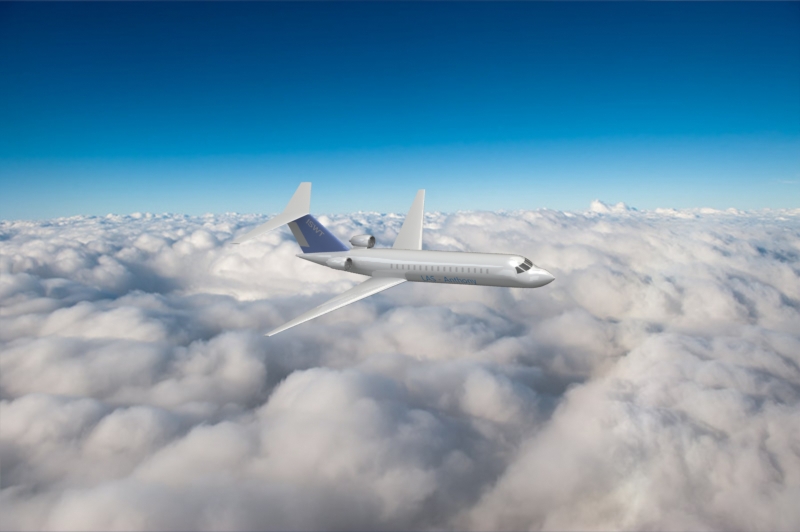
Maritime Surveillance Aircraft
This was a group project for my aircraft design class. We made a preliminary design of a Maritime Surveillance Aircraft (MSA), designed to loiter for long periods of time over open water. The main tradeoff in this design was the engine choice: turboprop vs. turbofan. Turbofan engines were selected based on the current market for MSAs as well as the desired performance of the plane. The interior of the aircraft can also be reconfigured as a regional airliner. The performance of our airplane was evaluated on a typical regional airliner mission, and it was found to outperform the CRJ-200 aircraft in cruise speed and service ceiling.

Design Proposal
Maritime surveillance needs around the world are rising, and many countries are looking to replace their aging fleets. To meet the needs of these customers, most designers seek to repurpose existing airframes for maritime surveillance use. Many business jets and turboprops in the medium to large commuter weight class are now being converted to Maritime Surveillance Aircraft (MSA) in order to capture an additional market with the same airframe and simplify development and production. Because the market for regional turboprops and bizjets is much larger than the market for MSAs, it makes sense to optimize an airframe for the larger market and then make modifications to meet the requirements of the smaller one. The Anthony Series of aircraft utilize the same airframe, with the LAS-Anthony as the MSA variant, and the TER-Anthony as the regional commuter variant. The only differences between the LAS and the TER are the fuel/payload capacity and internal configuration. All other performance parameters are the same.
Requirements
Because we are designing a dual purpose aircraft, there are two sets of requirements being targeted in parallel. There are the MSA requirements, and there are the commuter requirements. Some of the MSA requirements are 5000lb payload (2000 expendable), 300-600nm mission radius, 6hr minimum time on station, 60%-75% mission efficiency, Mach .6-.82, loiter altitude 0-3000, cruise altitude 30k-45k, TO/Ldg distance of 4000-6000, and stall speed of 85-140ktas. The commuter requirements were determined from competitors in a comparable weight class.
Design Methodology
Overview
The design of this aircraft concept was guided by an Excel spreadsheet by our team and a MATLAB program I wrote. The aircraft was designed to maximize MSA mission performance requirements, while simultaneously evaluating the aircraft performance on a commuter mission for benchmarking with competitors.
The Breguet Range Equation and Mission Profile Iterative Software
The aircraft design process is highly iterative and involves several steps which determine different characteristics of the aircraft; for example, wing shape and engine size. At the heart of this process lies the Breguet range equation and the iterative solver. This equation unifies all of the ‘detail design’ steps and evaluates the aircraft over a mission profile. Typically the Breguet range equation is used with the assumption that the aircraft is in steady state cruise for the entire mission, but of course this is only useful for back of the envelope calculations.
To ensure improve the accuracy of this method you must divide the mission profile into separate steady state sections and evaluate them separately. In this case, the mission profile consisted of a climb, a cruise to loitering location, descent to loiter altitude, a cruise (loiter), a climb to cruise altitude, a cruise return to base, and a descent. For the commuter variant, the mission profile was a simple climb-cruise-descent profile. The problem here is that there are more unknowns than knowns, and so an iterative solver must be used to guess/check and attempt to converge on a solution. The solver essentially says “given the defined mission profile and aircraft characteristics, this is how much fuel the aircraft must carry to execute the mission”. This in turn tells us how heavy the aircraft is when it takes off (MTOW).
Automation and Interconnection of Design Steps
After each adjustment, the initial iterative solver step must be re-run to evaluate performance and ensure the resulting characteristics are match the design and are physically possible. To give an example, the solver may produce an aircraft that requires 5000lbs of fuel to achieve its mission. However if in your aircraft sizing calculation, you had room for 4000lbs of fuel, you knew the design would not work and needed improvement. Much of the project was spent trying to connect all the different sections of the spreadsheet to ensure you didn’t accidentally design something physically impossible like a wing spar that’s thicker than the wing. One of the main functions of my MATLAB program was to error proof many aspects of the physical layout of the aircraft elements.
Design Point Selection
This MTOW is then used to select a design point. The design point is located in the plane formed by the aircraft wing loading and the T/W ratio. At this point the remain 3 variables, wing loading, thrust, and drag are all guesses. By selecting a design point at this stage, you are still just guessing at what the other three variables will be, but it’s more of a forward looking guess as you’re now setting the design goal.
Wing Geometry Definitization
In this step, the general wing planform geometry is defined, and the airfoil section is selected. Using the wing loading from the design point and the weight of the aircraft, the wing surface area S is calculated. Characteristics such as wing sweep angle, aspect ratio, taper ratio, thickness, dihedral, and mounting location are selected and the coefficient of lift of the wing is calculated using the standard incompressible, inviscid flow assumptions with potential flow theory. Many of these characteristics such as sweep angle and dihedral are just guesses at this point, as other aspects of the design will be driving forces for determining their final values.
Once the coefficient of lift is calculated, an airfoil may be selected by choosing an airfoil with a drag bucket coinciding with the coefficient of lift. Note that migration of the coefficient of lift must be accounted for; you do not want the coefficient of lift to migrate to the high drag regime of the airfoil.
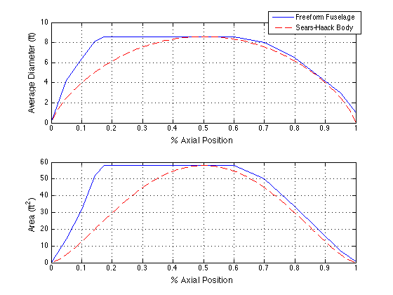
Fuselage Geometry Definitization
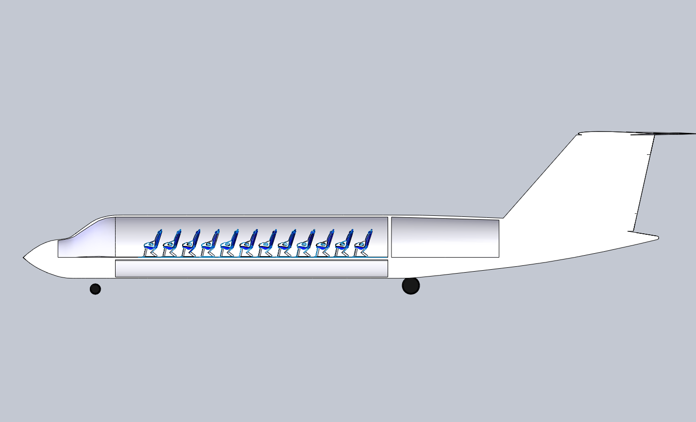
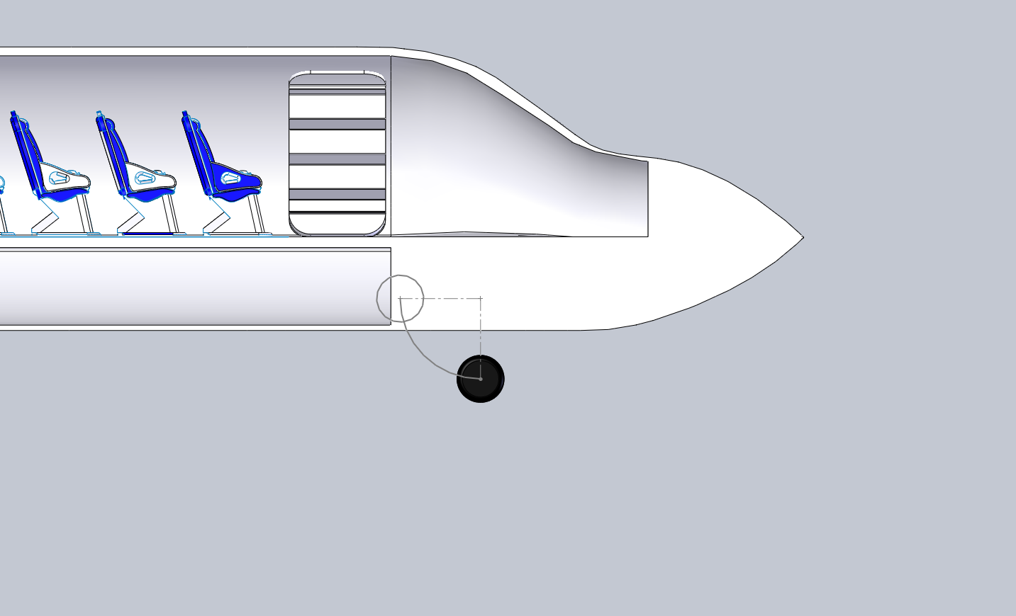
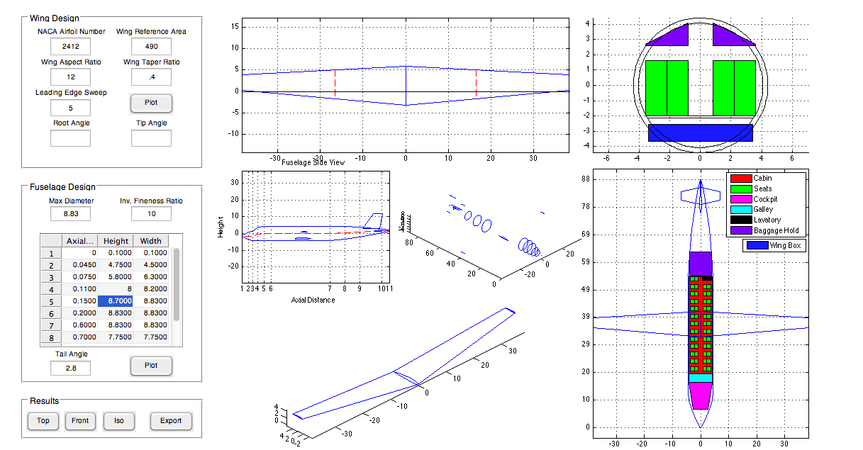
The fuselage size and shape were defined based on mission payload volume requirements. Using my MATLAB program, component layout within the fuselage was visualized and to aid in optimizing the layout to reduce fuselage length and associated drag. Here, the cabin configuration was planned, with envelope dimensions for seats, cargo areas, cockpit/crew areas, and galley/lavatory accommodations.
Drag Calculation
With most of the major structural elements of the aircraft now defined, a detailed drag analysis may begin. The remaining structural elements such as engines and control surfaces will have their sizes estimated during the first design iteration. Similar to the wing lift calculation, the drag calculations use the same assumptions of incompressible, inviscid flow. Correction factors are applied to account for transonic effects such as wave drag on swept wings.
Initial Control Surface Geometry and Location
The horizontal and vertical stabilizing surfaces are given a preliminary size estimate based on moment arm requirements and competitor aircraft dimensions. There is an inverse relationship between surface area and moment arm. It is generally in the best interest of the designer to maximize the moment arm in order to minimize the required control surface area. The designer is typically limited by the length of the fuselage, which the designer is usually trying to minimize for drag purposes, so the designer must strike a balance between these opposing forces. The horizontal and vertical stabilizer positions are then adjusted to ensure adequate effectiveness during stall and spin recovery.
Powerplant Selection and Sizing
In this step, the number, type, performance requirements, and configuration of the powerplants must be selected. The selection of the number of powerplants is primarily guided by the Federal Aviation Regulations. In the current regulator environment, twin engine aircraft are optimal. Having additional engines is usually not ideal as the drag contributions typically outweigh the thrust contributions. A single engine is not ideal due to complications certifying single engine aircraft for airline transport operations.
The next question is powerplant type. The main choices for this aircraft are turboprop vs. turbofan. This is the key design tradeoff for this aircraft and that will be discussed in a separate section below.
The performance requirement must then be selected. The powerplant is sized to meet cruise thrust performance and static takeoff thrust performance. For this project, the closest commercially available engine was selected and then scaled to the exact requirement. For the turboprop, a propeller was designed based on calculations using data from the Hamilton Standard propeller charts. These charts tell you the propulsive efficiency based on inputs of advance ratio and activity factor. The propulsive efficiency is then used to calculate aerodynamic thrust from power delivered by the powerplant shaft.
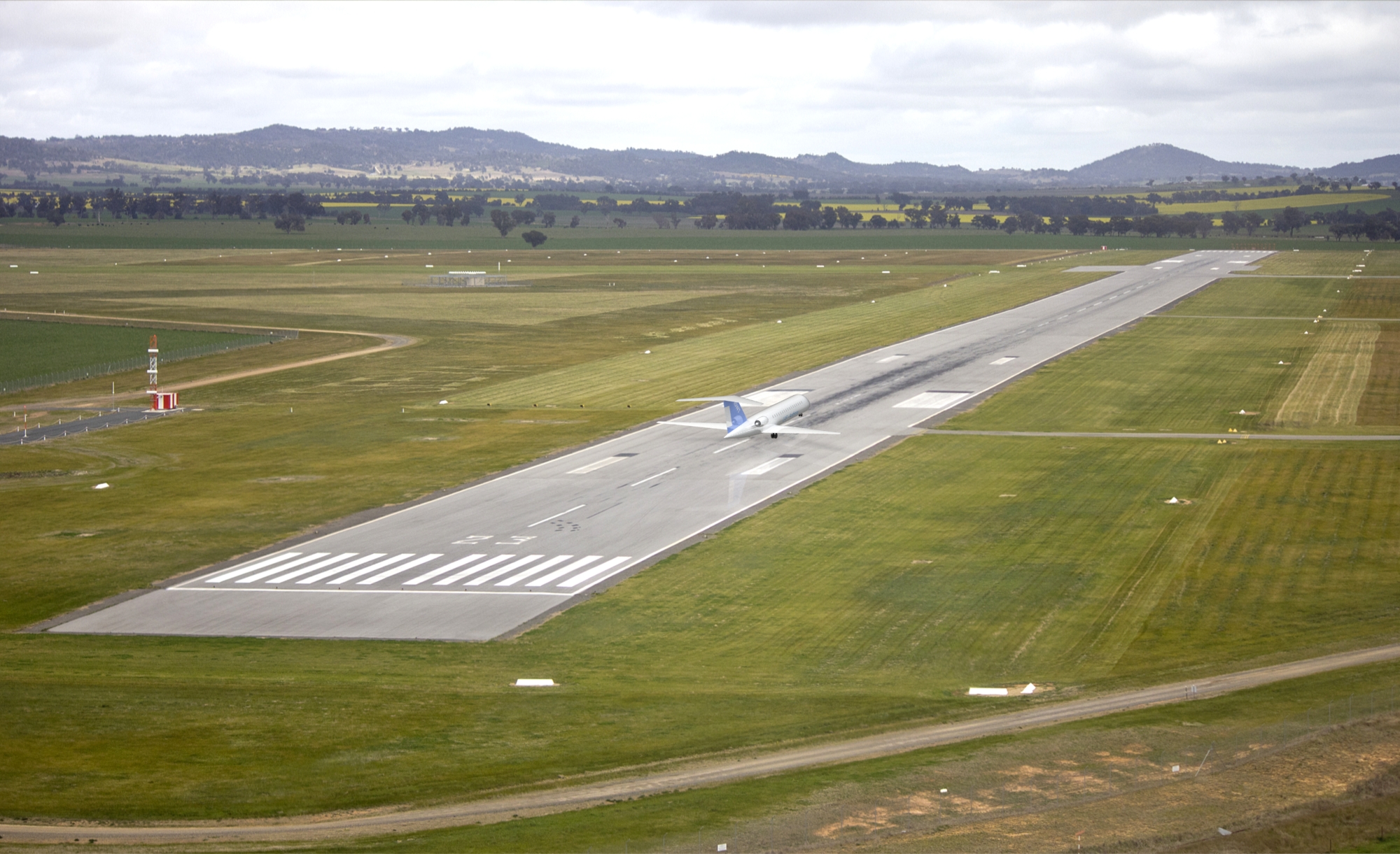
Takeoff and Landing Distance Calculation
Takeoff and landing lengths for AEO and OEI are calculated along with balanced field lengths. Enhanced lift devices are selected and sized to optimize takeoff and landing performance.
Structural Design, Analysis, and Materials Selection
Design load factor is calculated based on performance maxima and regulations. A V-n diagram is created. Bending loads for the wing and fuselage are calculated using the design load factor and component arrangement. Structural members (longerons, spars, skin) are designed and materials selected for each. Wing ribs and fuselage bulkhead geometry/weight was approximated here. One of the key outputs of this step is a more accurate empty weight estimate.
Longitudinal Stability Analysis
An empty weight fraction was calculated using correlations. Static stability analysis were performed to place internal components, the main wing (center of lift), and the tail surfaces. Note that aerodynamic lift and drag must be recalculated once the control surfaces are moved/scaled. This forms another iterative loop within the overall design process.
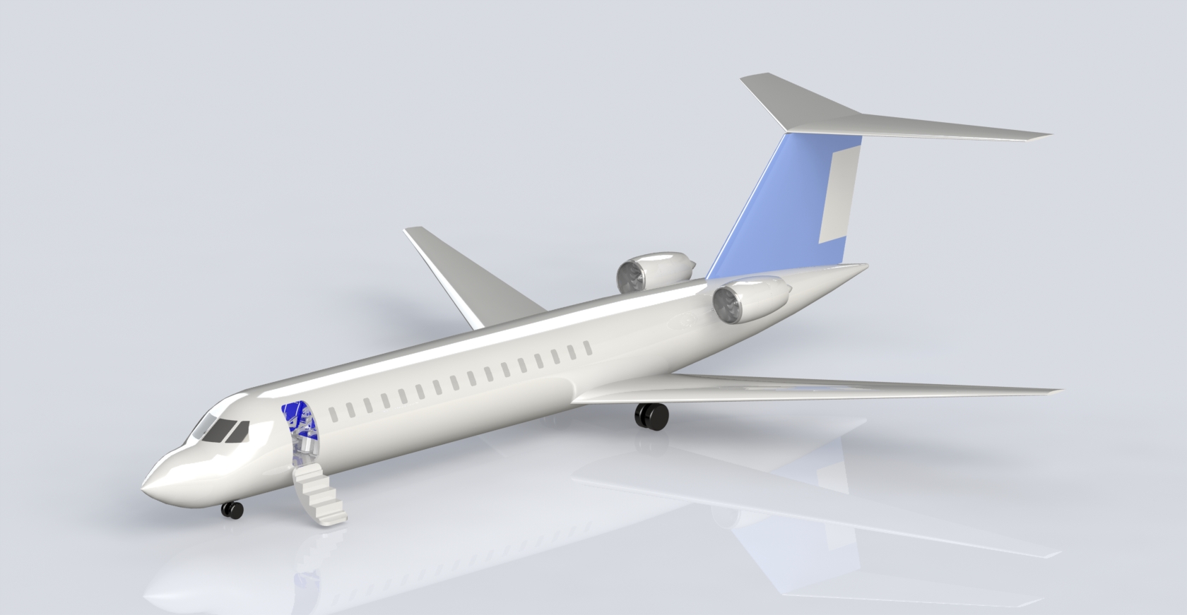
CAD Modeling
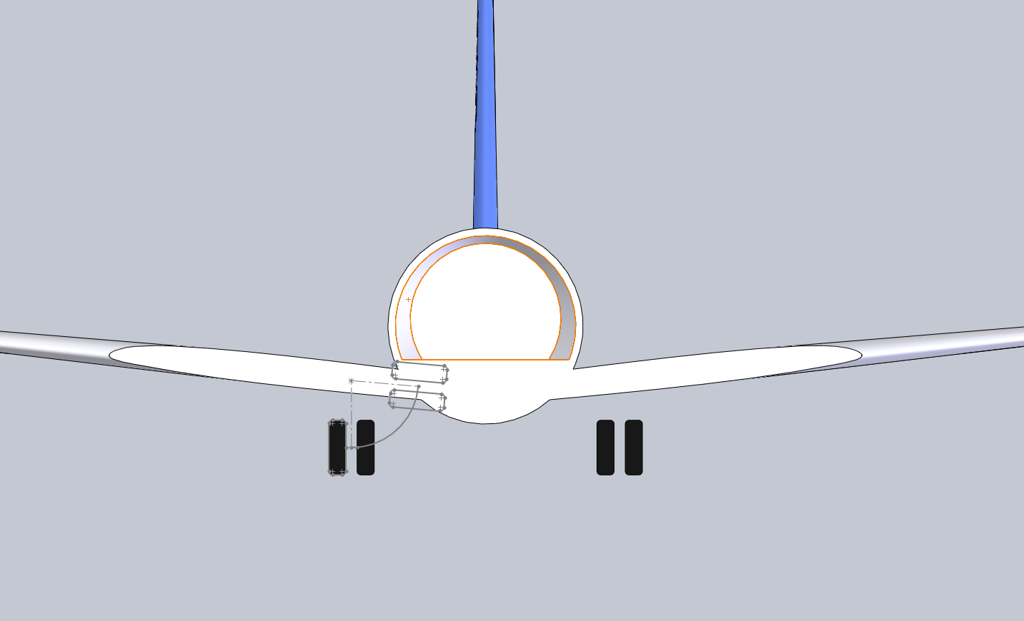
A CAD model and detailed design specifying component locations (landing gear, engines, etc) was created using the MATLAB software I created. The software generates coordinates for the wing and fuselage sections and exports the coordinates as text files. These text files may be imported into any CAD software as discreet profiles. These profiles can be combined using the loft function to generate the 3D model of the aircraft.
Cost Analysis
A cost analysis was performed to determine the production cost of the aircraft. This accounted for raw materials, labor, tooling and fixturing development, and amortization of production expenses. The analysis assumed 10% profit margin.
Design Tradeoffs
The main question to answer for this project was whether to use a turboprop, or a turbofan engine. The issue is that each engine is only efficient in a certain flight regime. Turbofans are only efficient during cruise and have poor SFC during loiter, resulting in increased fuel load and weight. Turboprops are more efficient in loiter than turbofans, but they are much slower, resulting in a lower mission efficiency. So throughout the project we were essentially designing two airplanes: a turboprop and a turbofan. Another tradeoff question to answer was regarding the payload. No MSAs in this weight class have sonobuoy capability. There is a choice to design for sonobuoys as a competitive feature, resulting in a slightly larger weight than the competitors, or eliminate the sonobuoys and attempt to minimize the weight. The other main tradeoff is between the cruise speed, engine size, and mission efficiency. Increasing the cruise speed will also increase the mission efficiency, but this will require a larger engine, resulting in more fuel and weight. I have a feeling that we will be more equipped to address these tradeoffs once we start the financial justification process. But is important to keep these tradeoffs in mind at all times, and to continually explore the design space.
Based on market research and MSA competitors, our team decided to go with a turbofan design. The market indicates that there is a growing demand for regional commuter jets, partially stimulated by the recent drop in oil prices. Additionally, our aircraft was designed to cruise on the upper limit of the range, in which turbofans are the obvious choice.
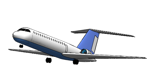
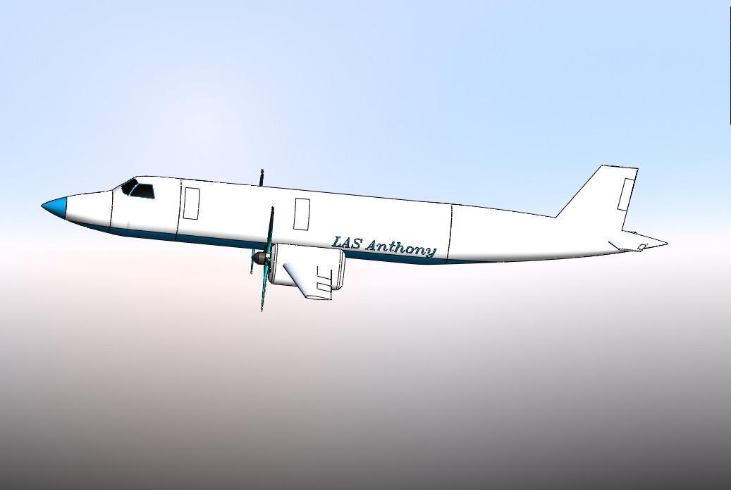
One aspect of the design that puzzled us was the longitudinal stability and control calculation. The procedure was to calculate the forces required for level flight at a variety of static margins, and plot a number of scatterplots for different parameters that varied with static margin. Then parabolas were fit to those scatterplots and stability at any center of lift location could be determined at any center of lift location using those curves. The center of lift location was optimized to produce a stable aircraft with the least trim drag. However, in order to keep our aircraft stable and lower the trim drag, the tail had to be moved very close to the wing and made quite large (as you can see in the photos). This increased drag caused our weight to increase as well, and overall had a very negative impact on the design. In addition, our static margin was extremely high (50%-75%). I also hope to one day write a MATLAB script to calculate longitudinal stability. Excel is a very poor tool for this type of calculation.
Specifications
LAS-Anthony (MSA) [Competitor Benchmark: Bombardier Challenger 605]
MTOW: 61,000lb [48,200lb]
Empty Weight: 33,000lb [26,985lb]
Payload: 4920lb, 1920lb expendable [1350lb, 0 exp.]
T/W: .44 [...]*
W/S: 90 [...]
Length: 88.7ft [68.42ft]
Wingspan: 80ft [64.33ft]
Engine Selection: 2x General Electric CF34-10A, (thrust scaled by 78.5%), 13,000lbg/eng TO [...]
Design Cruise Mach: .82 [.80]
Service Ceiling: 42,000 [41,000]
Crew: 11 [...]
Mission Efficiency: 62% [N/A]
Design Mission Radius: 500nm [N/A]
Loiter Altitude: 2,000 [N/A]
Materials: Fiberglass skin and wing spar, 2024-A1 Aluminum longerons [...]
TER-Anthony (Commuter) [Competitor Benchmark: Bombardier CRJ-200]
MTOW: 61,000lb [53,000lb]
Empty Weight: 33,000lb [30,500lb]
Payload: 13,500lb [13,500lb]
T/W: .21 [...]
W/S: 87 [...]
Length: 88.7ft [87.8ft]
Wingspan: 80ft [69.6ft]
Engine Selection: 2x General Electric CF34-10A, (thrust scaled by 78.5%), 13,000lbg/eng TO [2x General Electric CF34-3B1, 8,729lbf/eng TO]
Design Cruise Mach: .82 [.74]
Service Ceiling: 42,000 [41,000]
Passengers (Crew): 50 (4) [50 (4)]
Design Range: 1650nm [1644nm]
Materials: Fiberglass skin and wing spar, 2024-A1 Aluminum longerons [...]
*[…] signifies no competitor data available for that characteristic.