Microbend Mode Converter Device
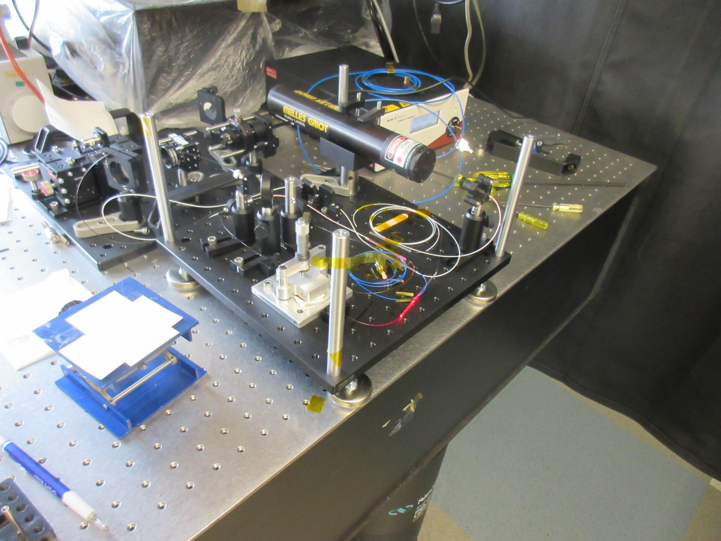
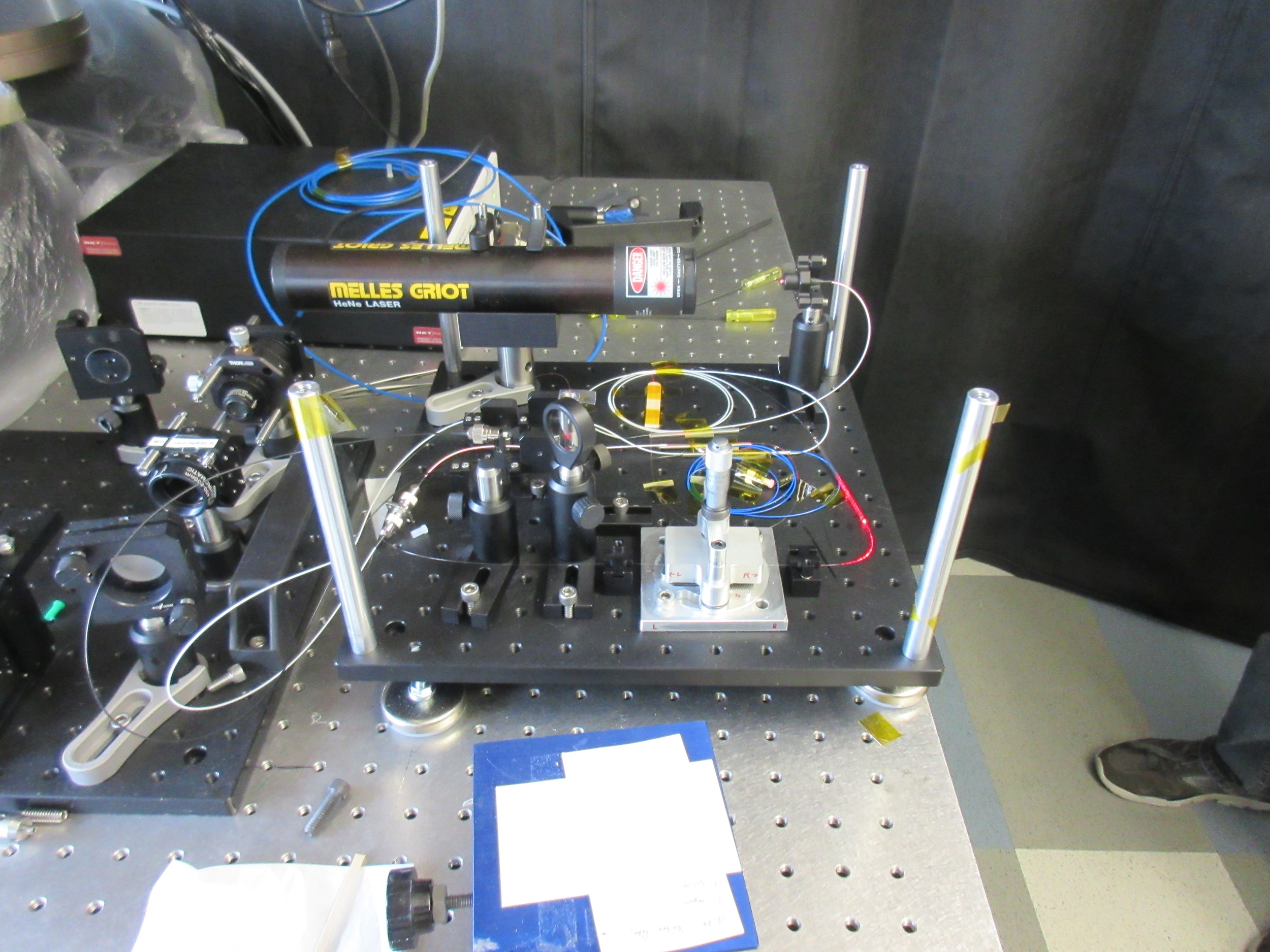
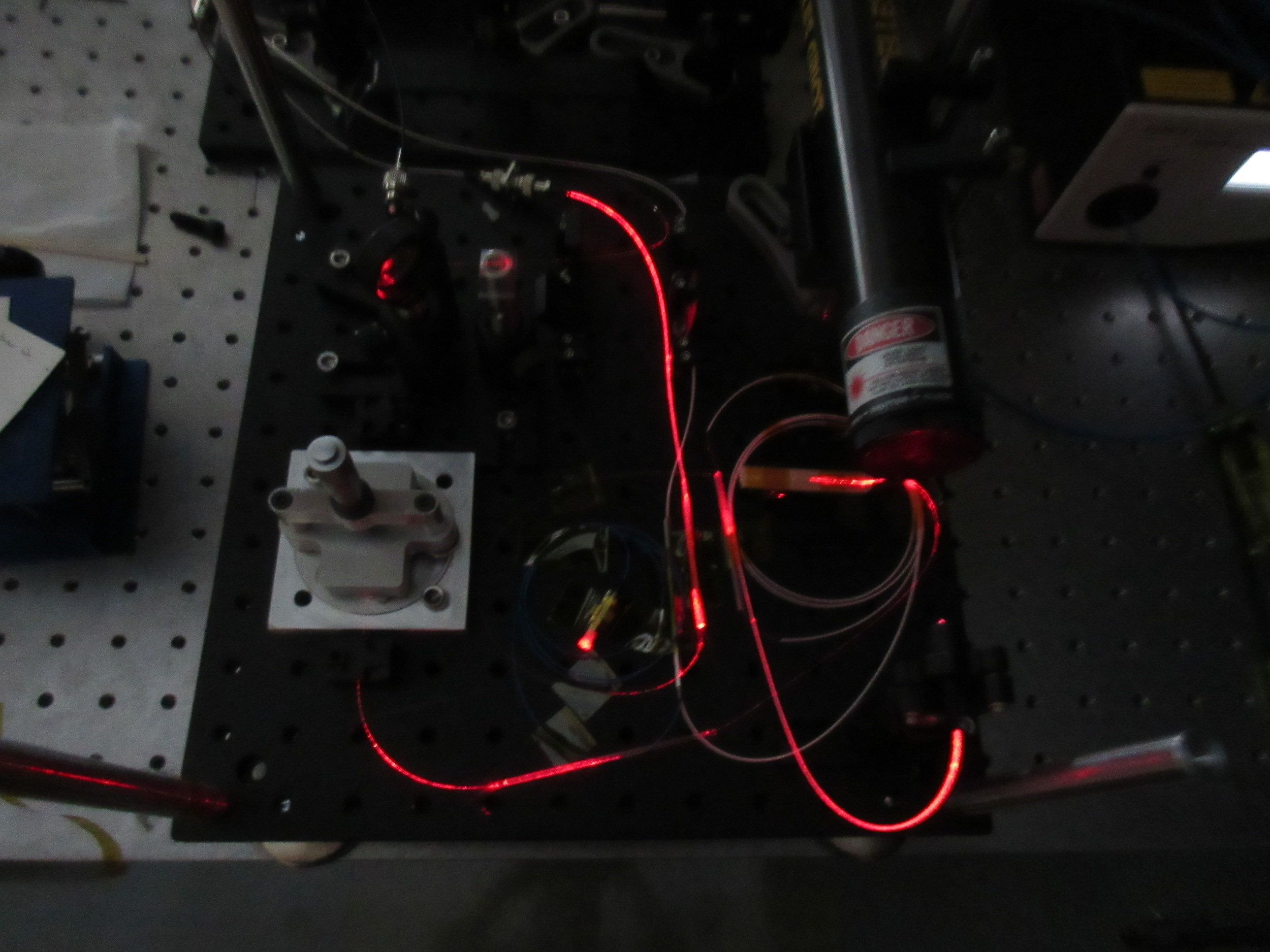
This was something I created as part of my job as an engineering education developer. It is a microbend mode mode converter for optical fibers. The device is part of a demo apparatus which is intended to teach students how optical fibers transmit light and data, as well as how researchers at BU are trying to increase the data capacity of optical fibers using a type of mode division multiplexing (MDM).


Introduction
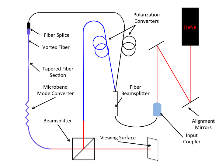
One of the outreach modules I worked on as an engineering education developer taught students about how fiber optic cables are able to guide light via total internal reflection, and how pulses of light could carry data. The activity also highlighted the ongoing research of Professor Siddharth Ramahandran in nanophotonics. I worked with researchers in Professor Ramachandran's group to help design and build an apparatus to visualize the interference of two different optical modes which can be used to increase the throughput of optical fibers.
Background
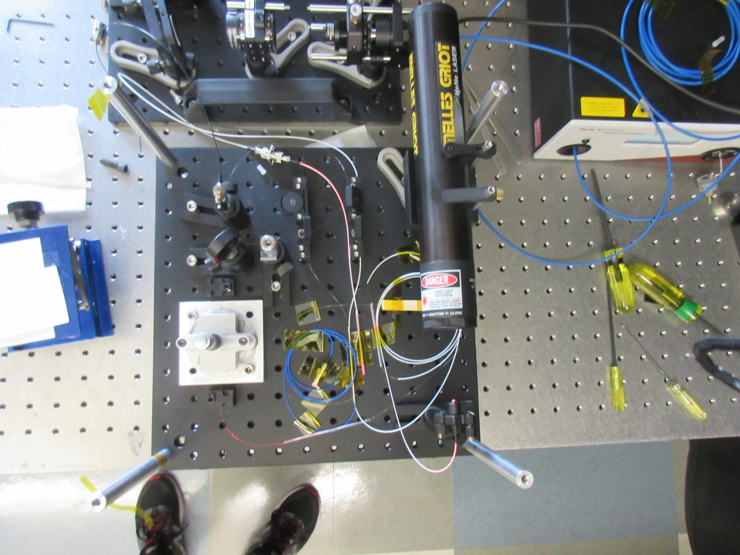
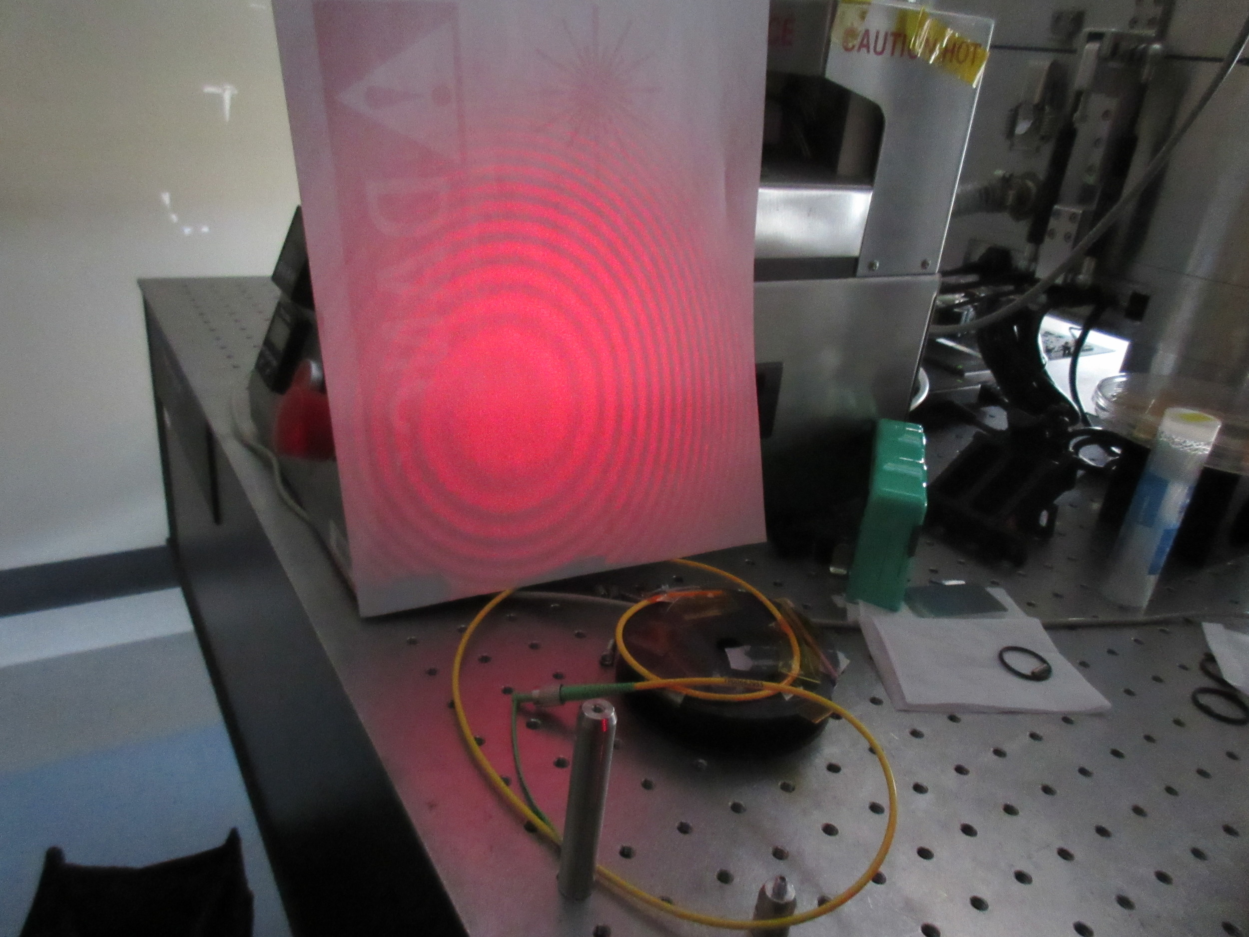
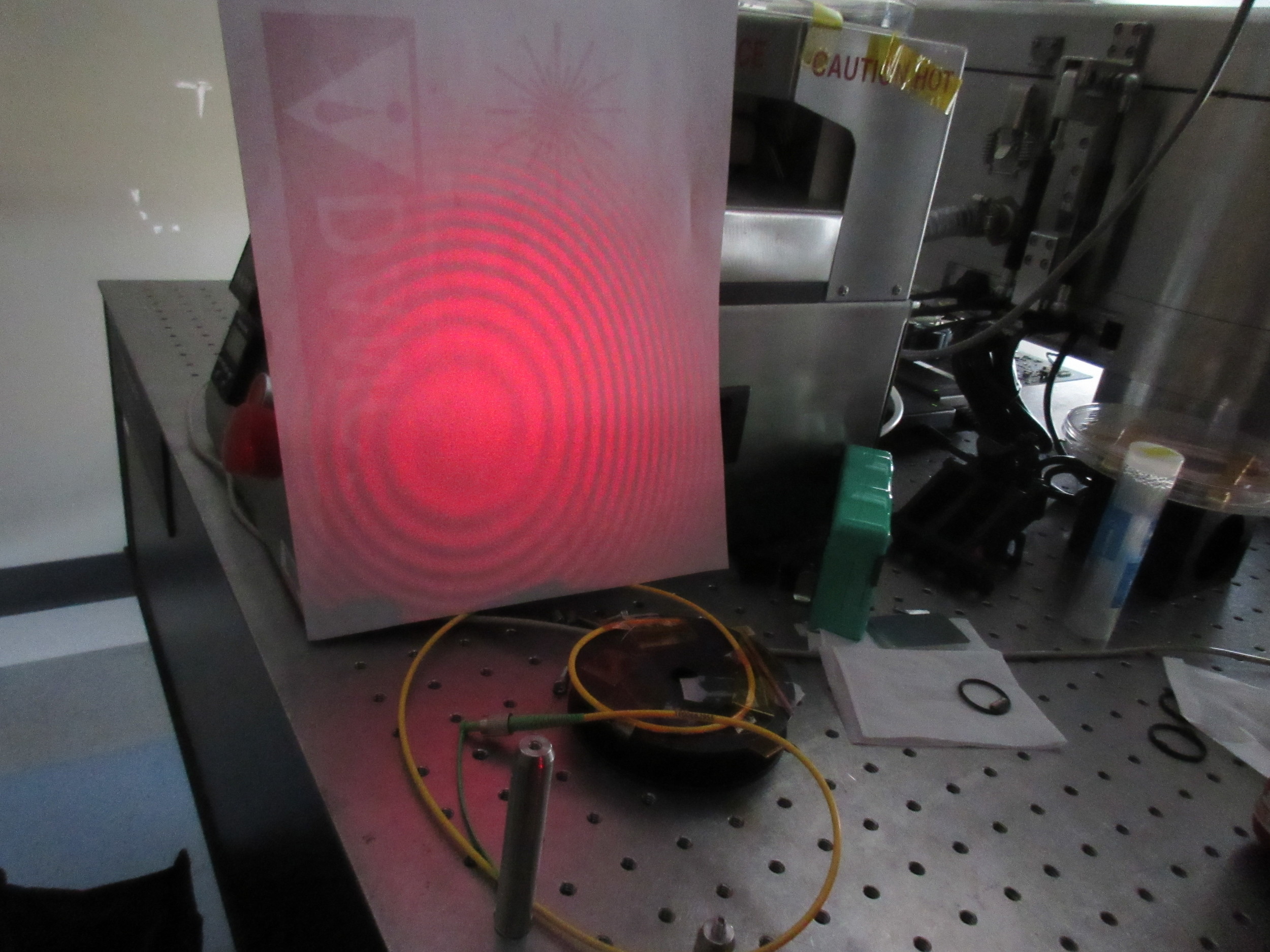
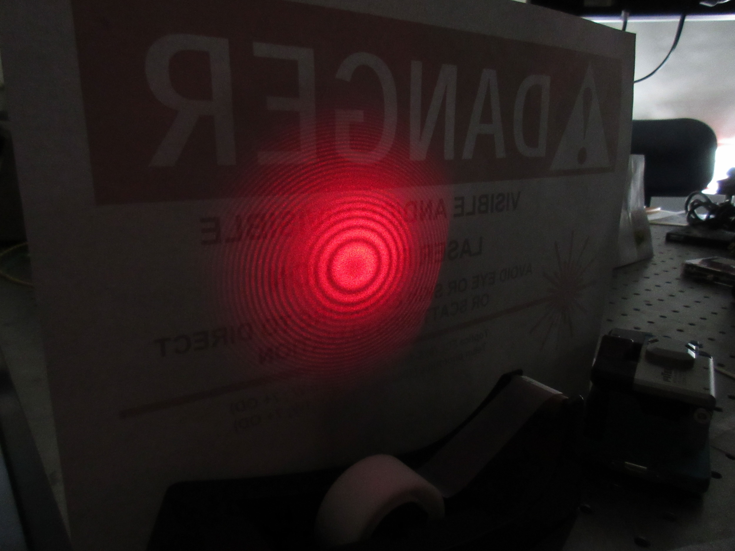
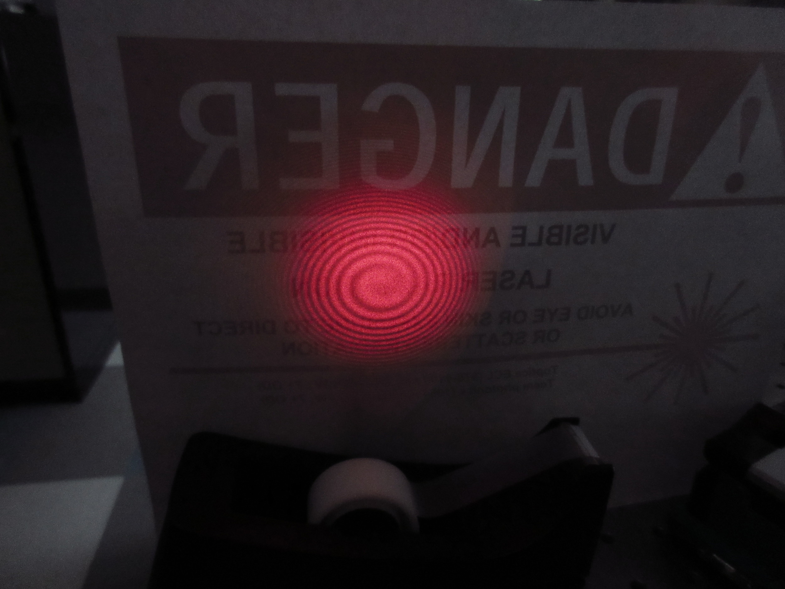
When I joined the project, most of the optical components had been purchased and assembled onto the breadboard already. The part that was missing was the microbend mode converter. The purpose of the mode converter is to change the mode of light traveling through the optical fiber. These transverse optical modes are like vibrational modes on a Chladni plate. Each mode has a distinct visual pattern. The other interesting thing is that when light travels through fibers this small, geometric optics cannot be used to describe the light. Instead, the light must be treated as an electromagnetic field and is described with Maxwell's equations.
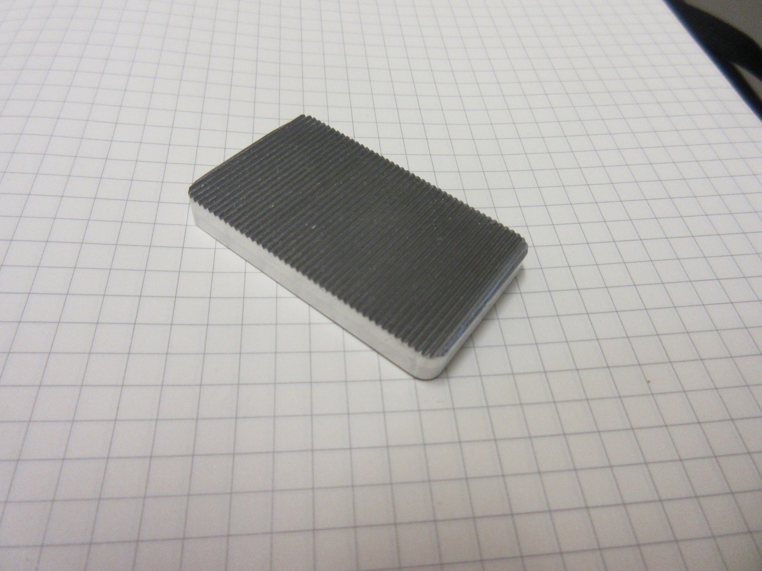
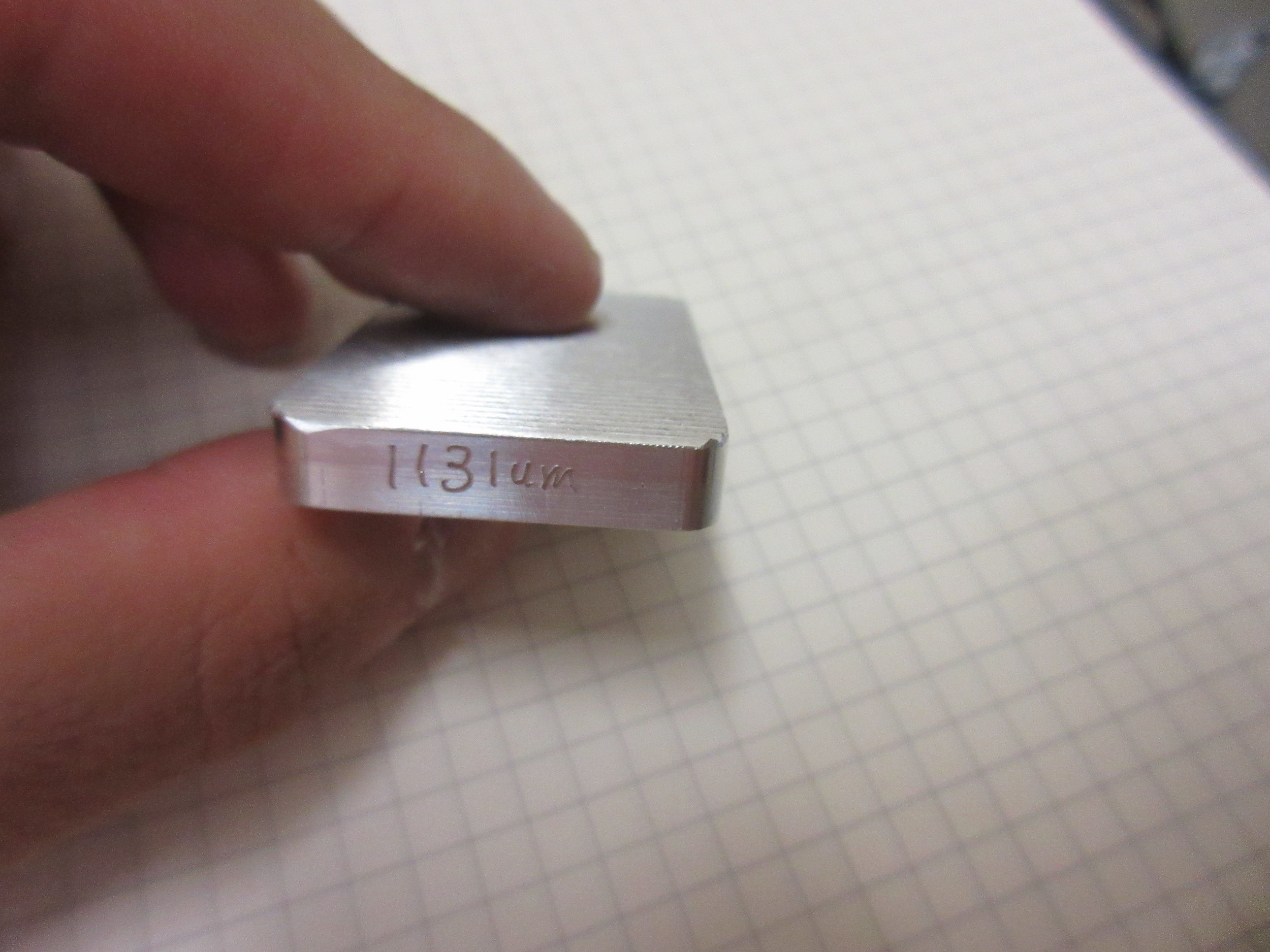
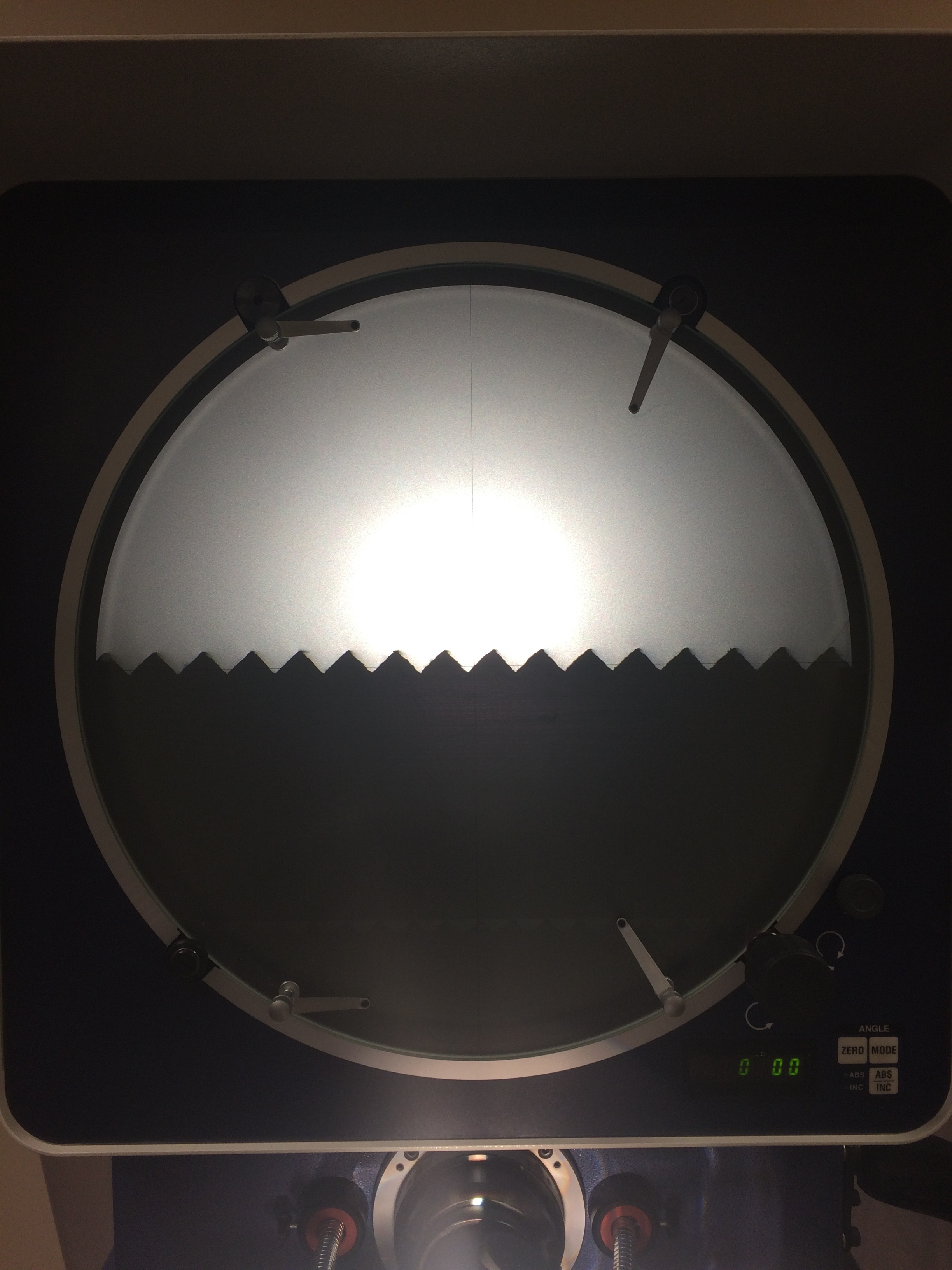
The mode converter works by creating lots of small bends in the fiber at a consistent interval. When the fiber experiences a [large] macrobend, there is total internal reflection (TIR) and the light is guided along the fiber. But in a microbend, the radius of curvature is so sharp that there is some change in the mode. It turns out that if you repeat these microbends at a certain interval very precisely, each bend gradually changes the mode a little bit in the same direction, until after several tens of microbends, the mode is effectively converted. The way this is accomplished is by making a grating plate with teeth spaced a precise distance apart. The fiber is pressed into the grating plate with an elastic material so that it conforms to the teeth of the grating plate. This way the fiber has many microbends at some fixed pitch.
Design
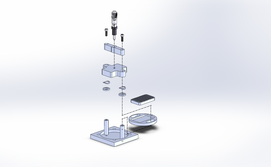
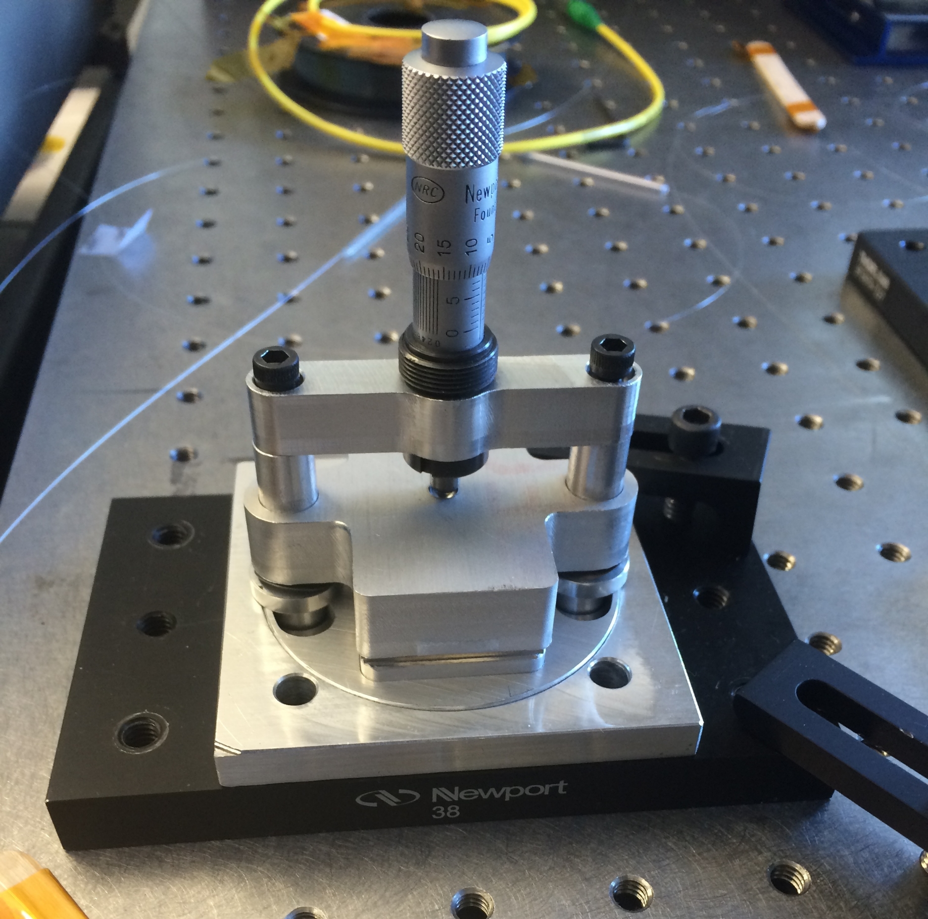
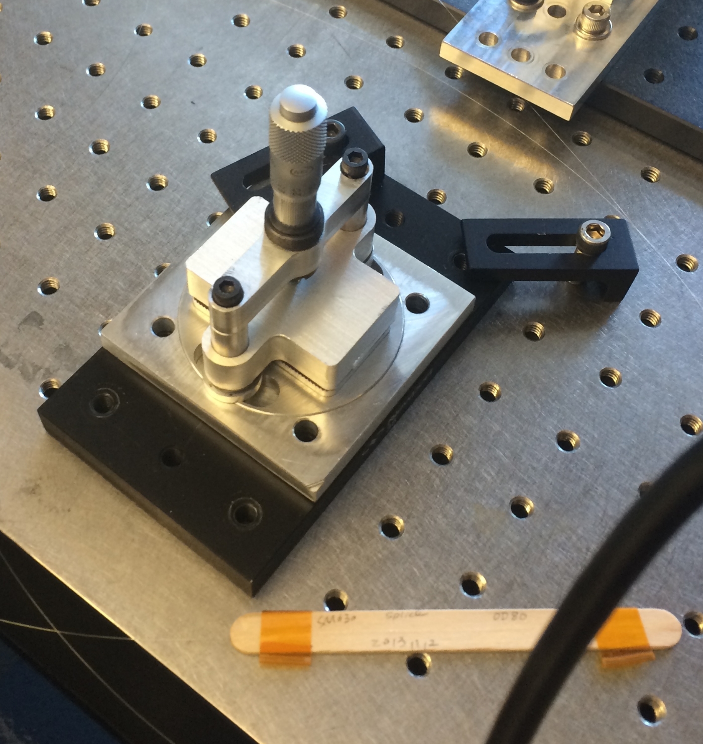
The goal of this design was to make a microbend mode converter device to be integrated into the rest of their assembly on the breadboard. I needed to make 3 grating plates with different pitches. This is sort of a coarse adjustment feature like on a microscope. The plates needed to be able to rotate to slightly change the effective pitch. This is like the fine adjustment knob on a microscope. Pressure needed to be applied to push the fiber into the grating plate. The amount of pressure needed to be controlled very precisely, as the optimal mode conversion would only occur at a very narrow range of pressures.
I decided to have the grating plates fit into a rotating disc for fine adjustment. The plates could be swapped out by hand for coarse adjustment. The pressure was applied by a micrometer head pushing on a block riding on two .375" precision ground posts. Tolerancing was very difficult for these components, because even the slightest amount of runout on the threaded holes in the optical posts could cause the pusher block to not slide freely. Even though I drilled and tapped the holes on the lathe to minimize hole runout, the pusher block would still bind depending on how the optical posts were screwed in. What we ended up doing was leaving the screws on the top of the micrometer mount slightly loose, so that the optical posts could bend as the pusher block was coming down rather than bind with it. The pusher block was idly resting on disc springs mounted around the optical posts, to keep it off the fiber while not in use.