Parallel Drafting Bars
This is a personal project I did to improve my machining skills and make something useful. This is a tool to help make technical drawings. Technical drawings often incorporate orthographic or isometric projection; which for most typical parts results in the need to draw parallel lines and lines at 30˚ or 60˚ angles. Doing this by hand or with only a straight edge or a protractor is difficult and time consuming. This tool consolidates some of the essential functions required by technical drawing and allows the user to user to make such drawings with ease and accuracy.


Motivation
I enjoy making engineering drawings by hand, but I'm no artist. If I'm going to draw, I need some tools to help me. For most drawings you really only need a straight edge, a protractor, and a rule if you're doing a scaled drawing. The straight edge helps draw perfectly straight lines, and the protractor helps draw them at the desired angle. However, if you're drawing on paper without grid lines, it can be difficult to make sure your horizontal and vertical lines are parallel to each other. I never liked the method of dragging the straight edge across, trying to keep it parallel to the line you just drew. I decided to combine the 3 essential functions (straight lines, 30˚ angle, parallel lines) required for making basic drawings into one tool.
Design
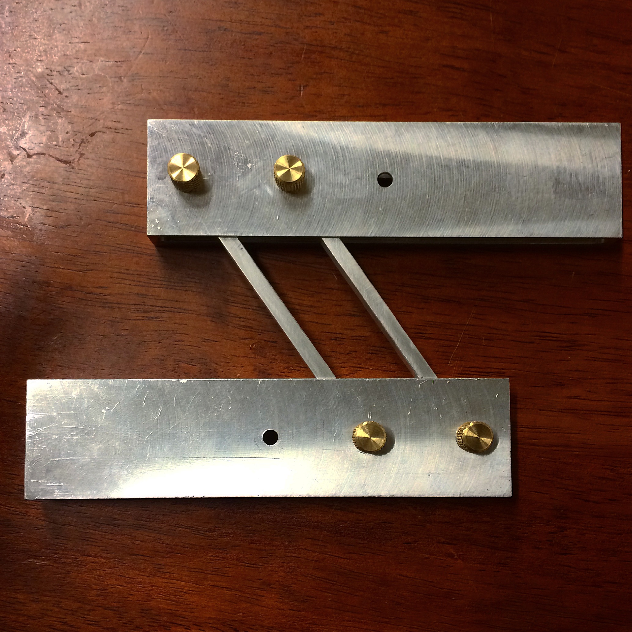
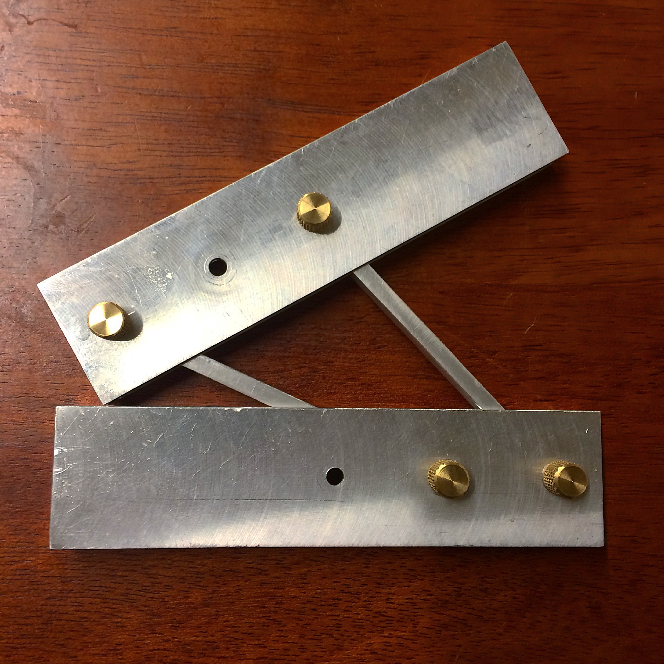
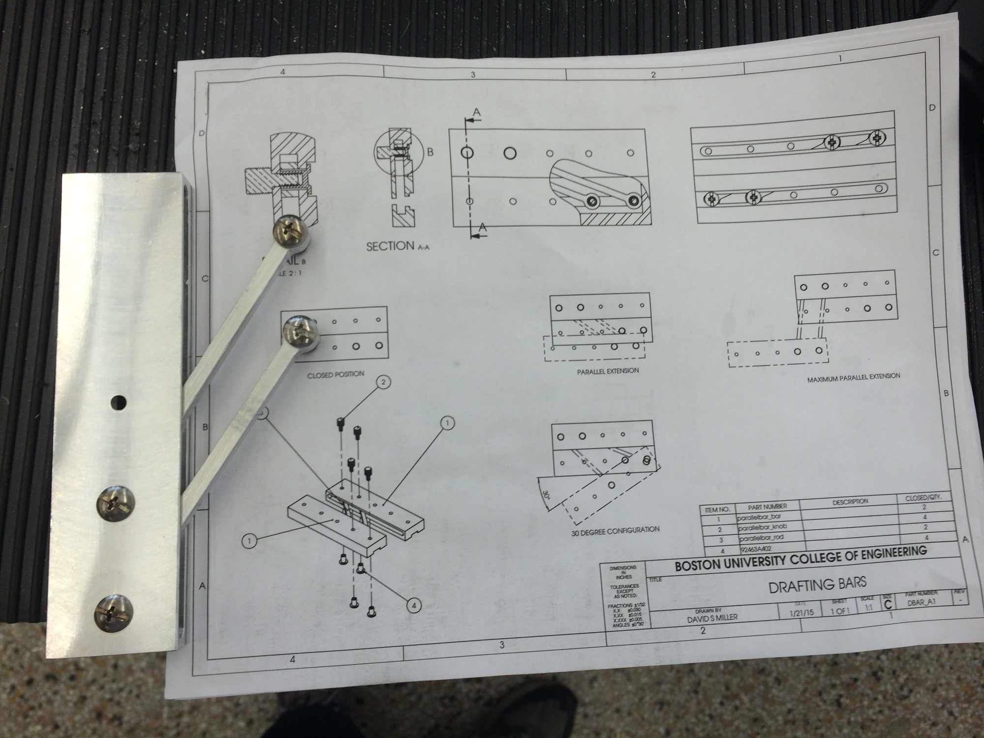
The tool consists of two rectangular bars connected by a parallelogram linkage; the simplest of the four bar linkage family. In this linkage, the coupler and the frame are the two bars, and the cranks are connecting rods between the bars. The connecting rods are held in position by binding posts and thumbscrews. Tightening the thumbscrew compresses the thin material of the bar such that it makes contact with the surface of the connecting rod. The friction at the interfaces provides a means of locking the bars in a certain position. In this way, the bars can be used as calipers to measure and copy distances between parallel lines. To measure distances less than the widths of the bars, one can use the interior edges rather than the exterior edges. To obtain the 30˚ angle, simply unscrew one of the rods and move it to the center hole location. Then rotate the bars until they touch, and you have your 30˚ angle! See my original blogpost for more information on the design.
Notes for Future Designs
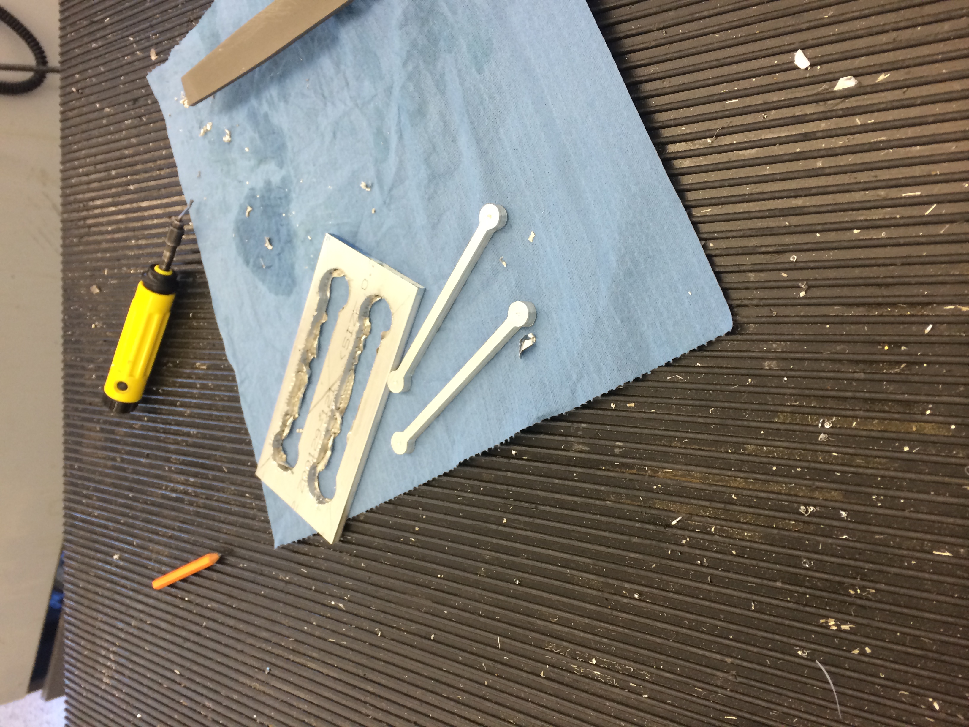
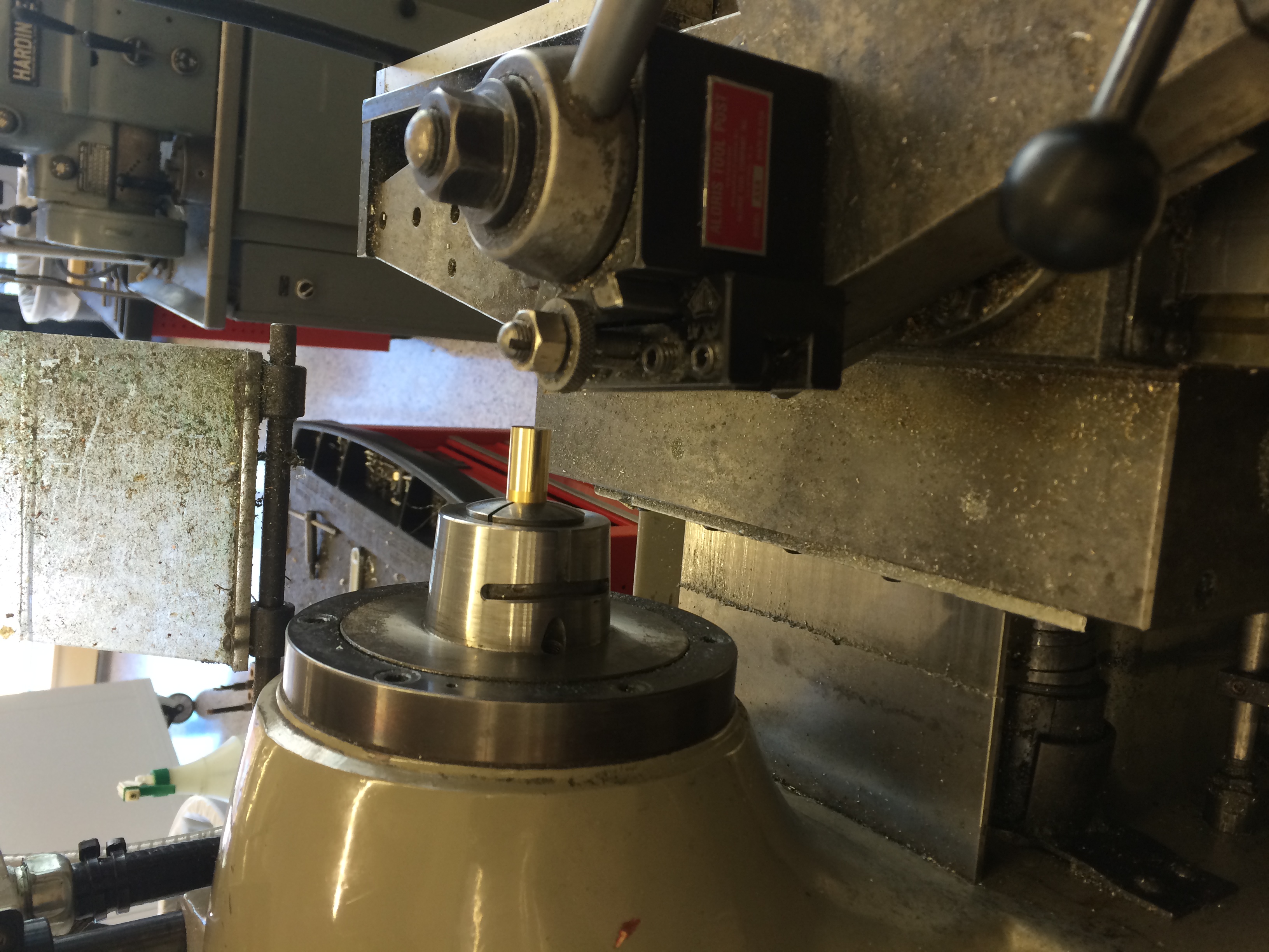
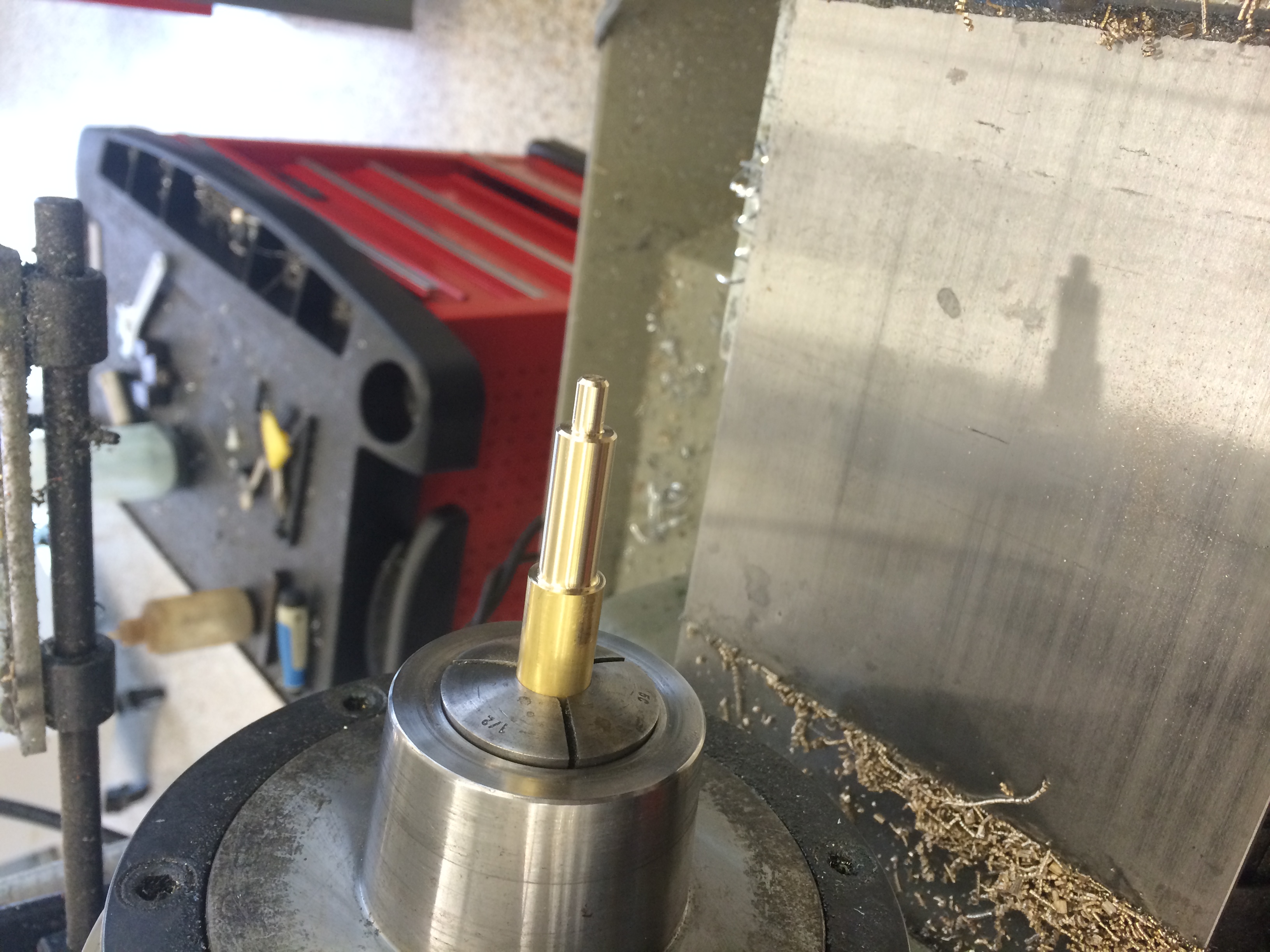
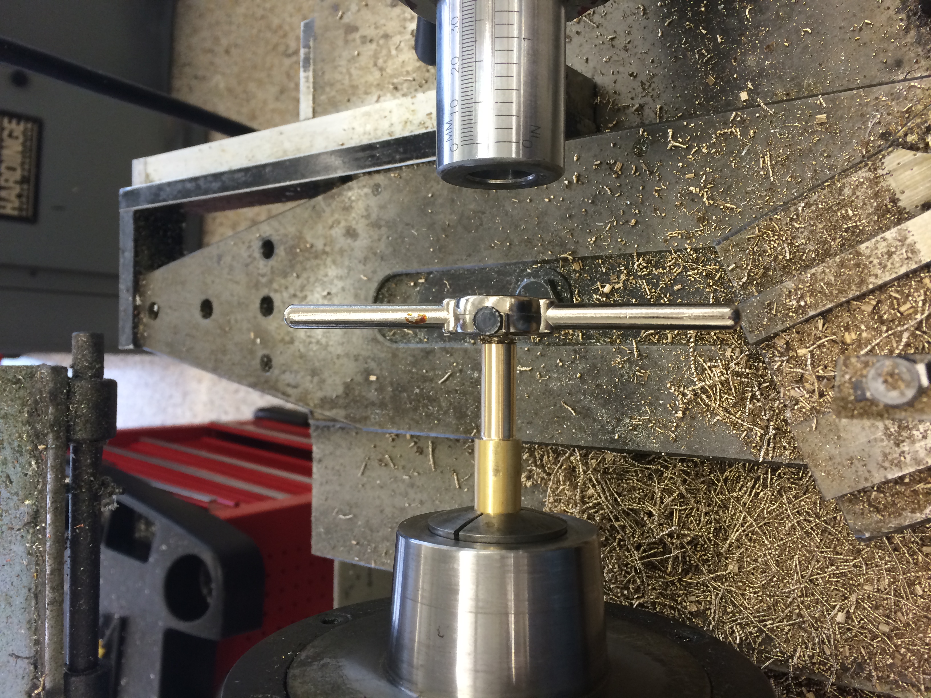
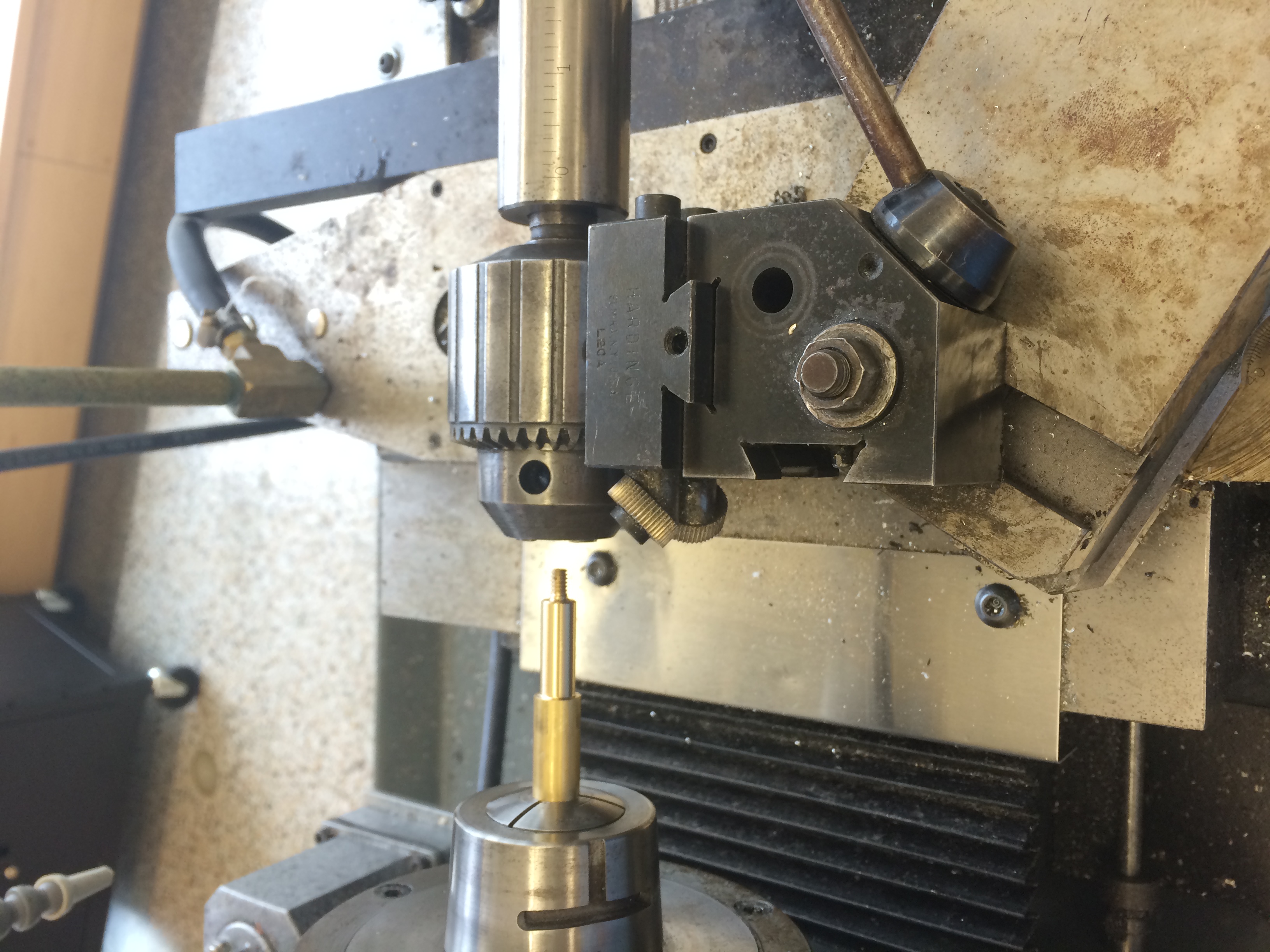
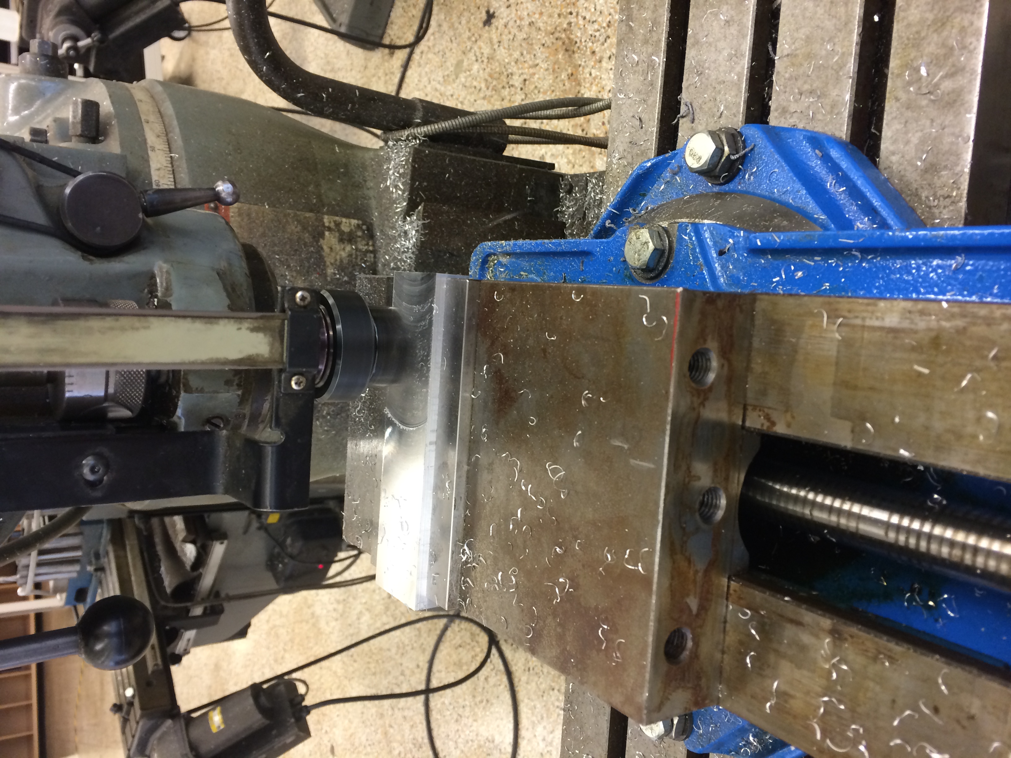
Milling the horizontal slot that houses the connecting rods was very time consuming and produced a rough finish. The next design will split the bar into two halves so the slot can be face milled rather than side milled. Additionally, the binding posts have a low circularity tolerance, making it difficult to get a close fit with the reamed holes of the connecting rods. This leads to play in device. The open channel results in the binding posts falling out. A T slot machined on the opposite surface could retain the binding post, but tooling to mill such a small (1/8" headspace) T slot is nonstandard. A 1/4" T slot cutter (.23" headspace) could be used, but that may make the bars too thick. I'd also like the tool to incorporate more functions, such as drawing circles and ellipses.